Magnetic disk drive

a magnetic disk drive and magnetic technology, applied in the direction of maintaining the head carrier alignment, recording information storage, instruments, etc., can solve the problems of slow response speed vs coarse adjustment control system, and the time period necessary for positioning the magnetic head cannot be reduced, so as to reduce the time period necessary for positioning the magnetic head

Inactive Publication Date: 2009-12-01
WESTERN DIGITAL TECH INC
View PDF2 Cites 0 Cited by
  • Summary
  • Abstract
  • Description
  • Claims
  • Application Information

AI Technical Summary

Benefits of technology

[0009]Embodiments of the present invention help to provide a magnetic disk drive that is capable of reducing a time period necessary for positioning a magnetic head when positioning the magnetic head by use of a dual-stage actuator. According to the particular embodiment shown in FIG. 3, a main control circuit 10 of a magnetic head device selects one of a seek mode and a positioning mode. The seek mode is to set a coarse adjustment control system VS to be a stable system by not causing control of a piezoelectric actuator 30 to be performed by a fine adjustment control circuit 42. The positioning mode is to set the coarse adjustment control system VS to be an unstable system and setting a total control system inclusive of the coarse adjustment control system VS and a fine adjustment control system PS to be the stable system by causing the control of the piezoelectric actuator 30 to be performed by the fine adjustment control circuit 42. As a result, the main control circuit causes the control system to operate.

Problems solved by technology

Nevertheless, however, the thus designed coarse adjustment control system VS is slow in response speed in comparison to the fine adjustment control system PS, such that the operation of the course adjustment actuator V serves as hindrance to the extent of increasing a time period necessary for positioning the magnetic head.
A technique can be contemplated that causes the coarse adjustment actuator V to substantially not operate, but causes the positioning of the magnetic head to be achieved only with operation of the fine adjustment actuator P. However, only with the operation of the fine adjustment actuator P, the time period necessary for positioning the magnetic head cannot be reduced.

Method used


Image

  • Magnetic disk drive
  • Magnetic disk drive
  • Magnetic disk drive

Examples


Embodiment Construction

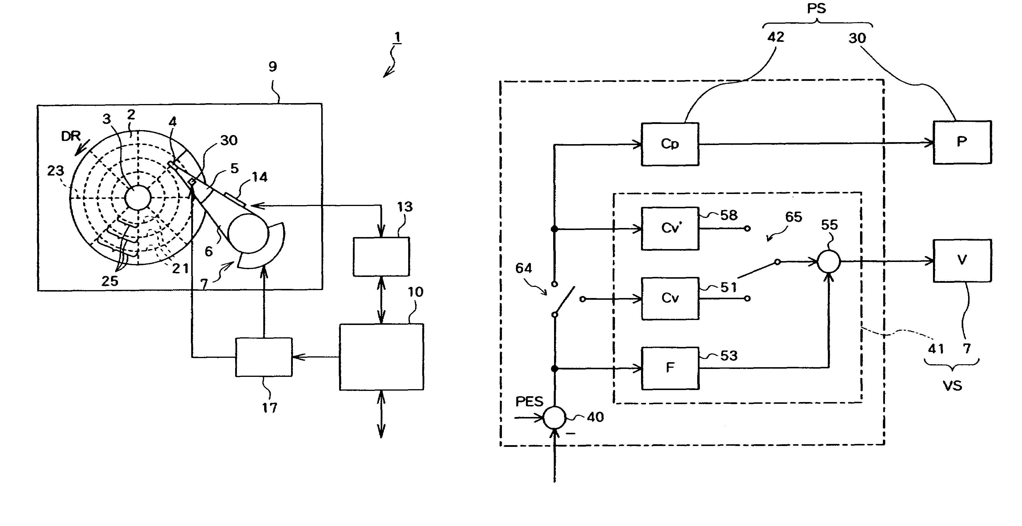
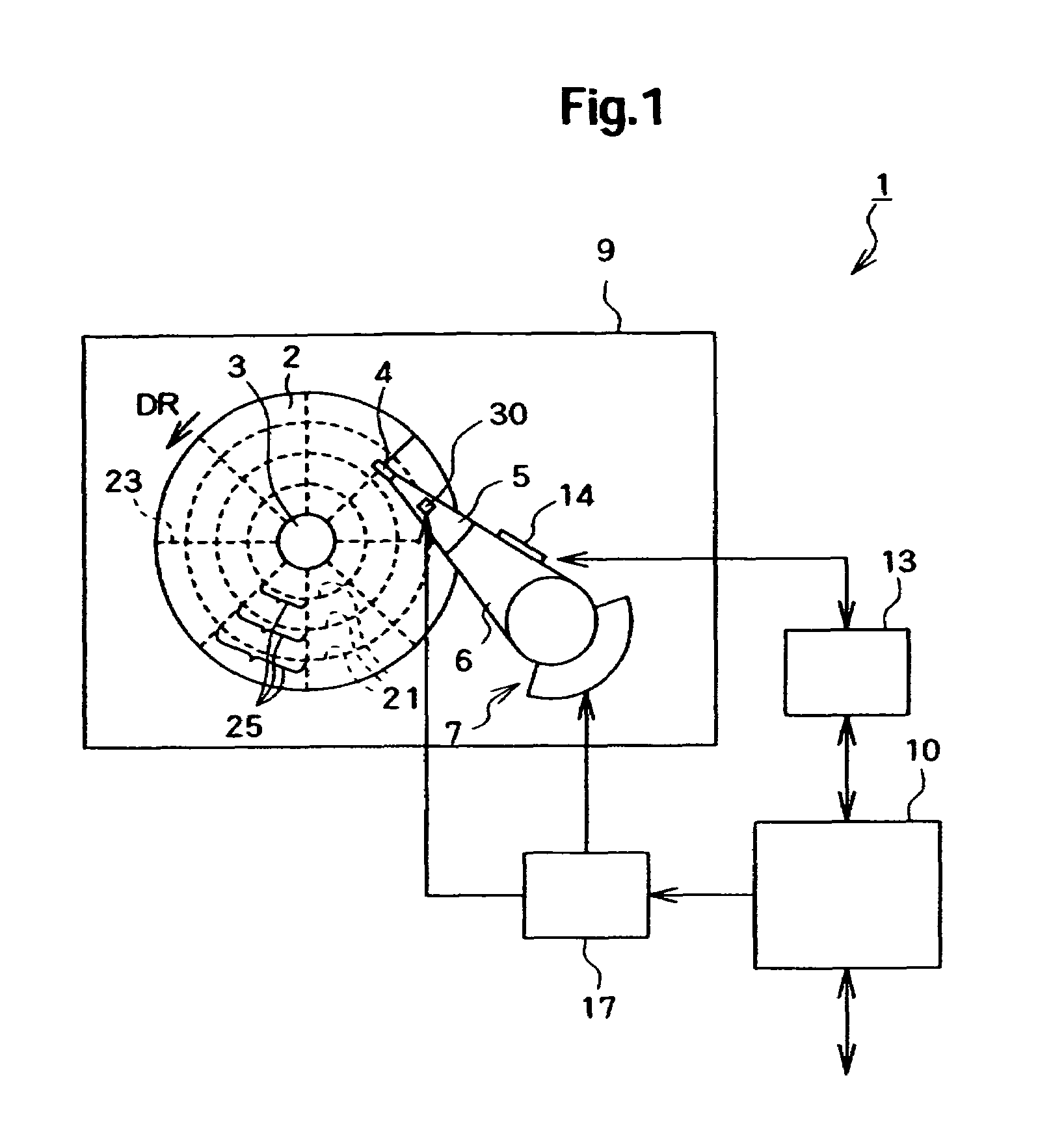
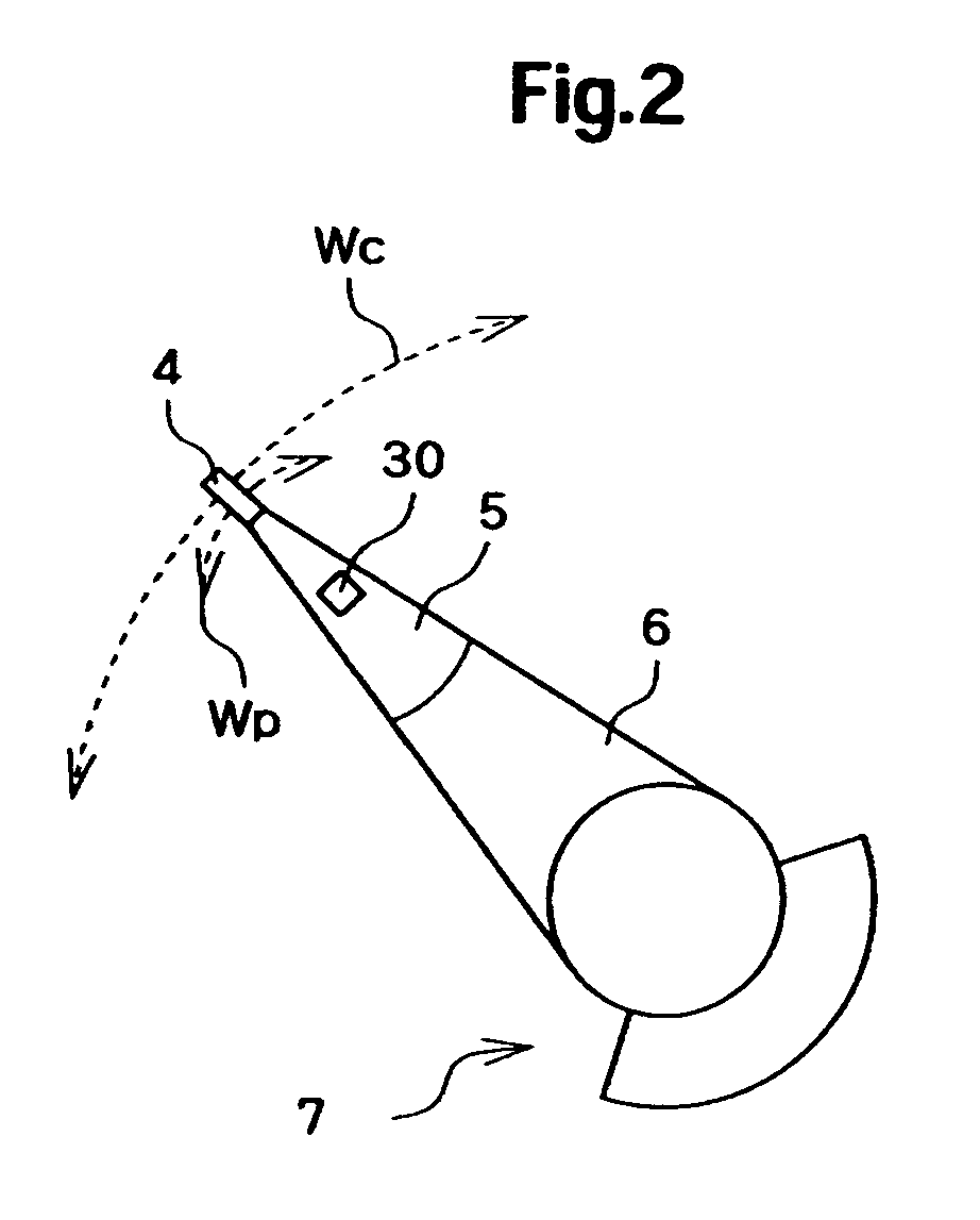
[0018]Embodiments of the present invention relate to a magnetic disk device.

[0019]Embodiments of the present invention are made in view of the circumstances described above. Accordingly, one object of embodiments of the invention is to provide a magnetic disk drive that is capable of reducing the time period necessary for positioning a magnetic head when positioning the magnetic head by use of a dual-stage actuator.

[0020]In order to solve the problems described above, a magnetic disk drive according to an embodiment of the present invention is characterized by including a magnetic disk medium; a magnetic head for reading out information recorded in the magnetic disk medium; an arm for supporting the magnetic head; a first actuator for actuating the arm to perform control of a position of the magnetic head on the magnetic disk; a second actuator for adjusting the position of the magnetic head on the arm; a position error signal generation circuit for generating a position error signa...


PUM

PropertyMeasurementUnit
speedaaaaaaaaaa
widthaaaaaaaaaa
response speedaaaaaaaaaa

Abstract

Embodiments of the present invention help to provide a magnetic disk drive that is capable of reducing a time period necessary for positioning a magnetic head when positioning the magnetic head by use of a dual-stage actuator. According to one embodiment, a main control circuit of a magnetic head device selects one of a seek mode and a positioning mode. The seek mode is to set a coarse adjustment control system to be a stable system by not causing control of a piezoelectric actuator to be performed by a fine adjustment control circuit. The positioning mode is to set the coarse adjustment control system to be an unstable system and setting a total control system inclusive of the coarse adjustment control system and a fine adjustment control system to be the stable system by causing the control of the piezoelectric actuator to be performed by the fine adjustment control circuit. Thereby the main control circuit causes the control system to operate.

Description

CROSS-REFERENCE TO RELATED APPLICATION[0001]The instant nonprovisional patent application claims priority to Japanese Patent Application No. 2007-110783 filed Apr. 19, 2007 and which is incorporated by reference in its entirety herein for all purposes.BACKGROUND OF THE INVENTION[0002]A hard disk drive for a magnetic disk, such as a hard disk, has a voice coil motor for driving an arm that supports a magnetic head. The voice coil motor is controlled to position the magnetic head onto a desired position over the magnetic disk, whereby recording / playback of information is performed thereon.[0003]In recent years, there have been proposed magnetic disk drives of the type that, in addition to a coarse regulation actuator, such as a voice coil motor and the like, has a fine adjustment actuator, i.e., so-called two-stage or dual-stage actuator, formed from a piezoelectric element or the like and provided to the arm for further improving the positioning accuracy.[0004]FIG. 8 shows the magnet...

Claims


Application Information

Patent Timeline
Patent Type & Authority Patents(United States)
IPC IPC(8): G11B21/02G11B5/596
CPCG11B5/556G11B5/4873
Inventor KISAKA, MASASHI
Owner WESTERN DIGITAL TECH INC
Why Eureka
Try Eureka