
Database processing method and database processing system

Active Publication Date: 2010-11-18
HITACHI LTD
View PDF6 Cites 13 Cited by
  • Summary
  • Abstract
  • Description
  • Claims
  • Application Information

AI Technical Summary

Benefits of technology

[0008]In the database processing system, in a case of search for specific data from among data stored in a table, an index is created in order to reduce the number of I / O requests issued along with the search processing and to shorten a search time period. However, in a case where a large amount of data is handled, even if an index is used for search, a considerable number of I / O requests are issued.
[0009]In order to shorten the I / O request processing time period in a case where I / O requests are queued and scheduled, it is effective to queue all I / O requests necessary for the search processing and to schedule all the queued I / O requests. However, it takes a long time period to queue all the I / O requests, and further takes a considerably long time period to schedule the considerable number of I / O requests.
[0011]This invention has been made in view of the problems described above, and it is therefore an object of this invention to shorten a time period necessary to process I / O requests in a manner in which a database processing system controls an issuance order of the I / O requests.
[0013]According to the aspect of this invention, the request to acquire the data is sent to the storage system for each of the plurality of partial indices created based on the storage location of the data, and accordingly, a scheduling function provided by the storage system is utilized, to thereby allow a time period necessary to input and output the data to be shortened.

Problems solved by technology

However, in a case where a large amount of data is handled, even if an index is used for search, a considerable number of I / O requests are issued.
However, it takes a long time period to queue all the I / O requests, and further takes a considerably long time period to schedule the considerable number of I / O requests.
However, in this method, only a part of I / O requests are focused as a target of the scheduling processing, and hence the entire I / O request processing time period cannot necessarily be shortened.

Method used


Image

  • Database processing method and database processing system
  • Database processing method and database processing system
  • Database processing method and database processing system

Examples


first embodiment

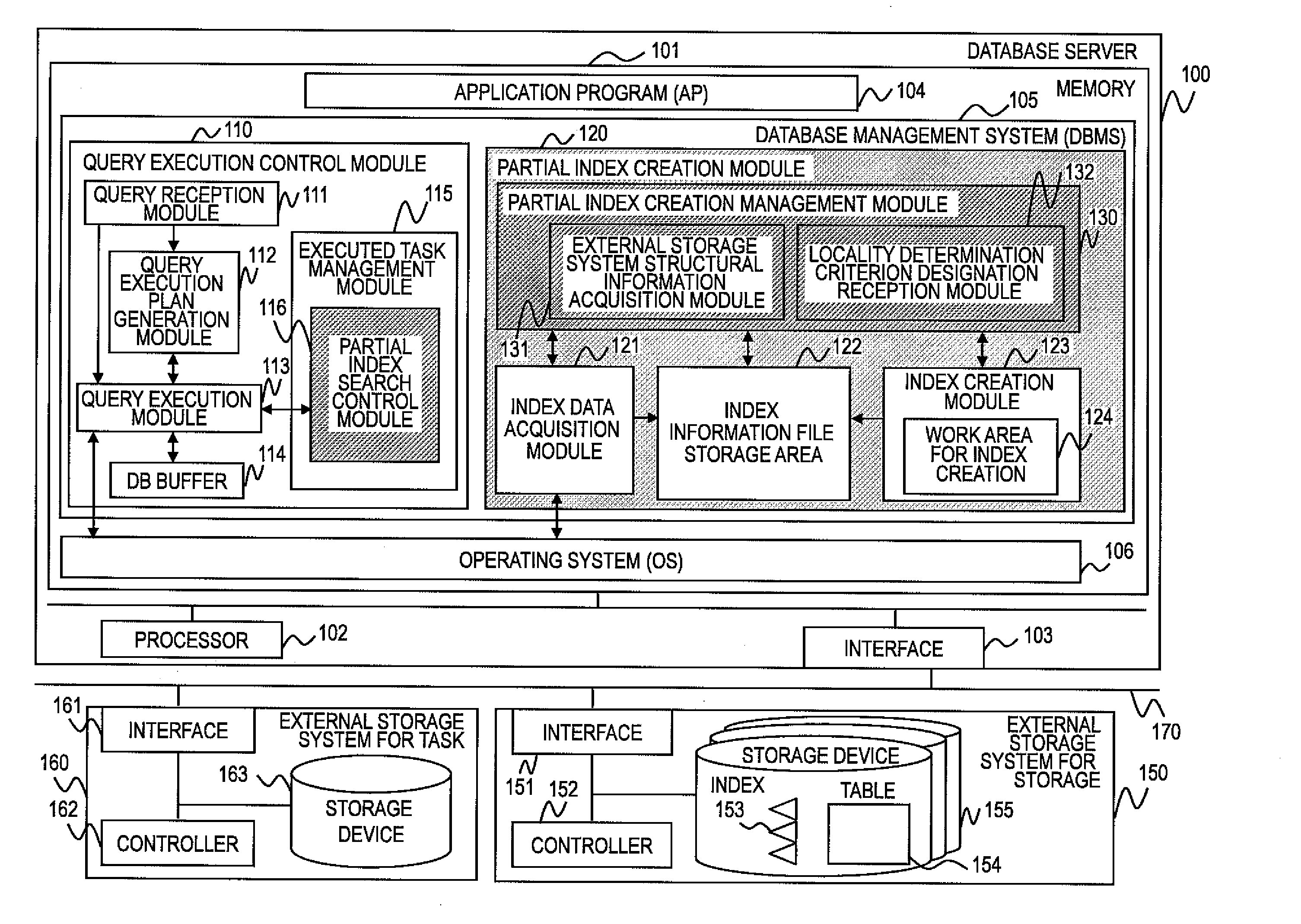
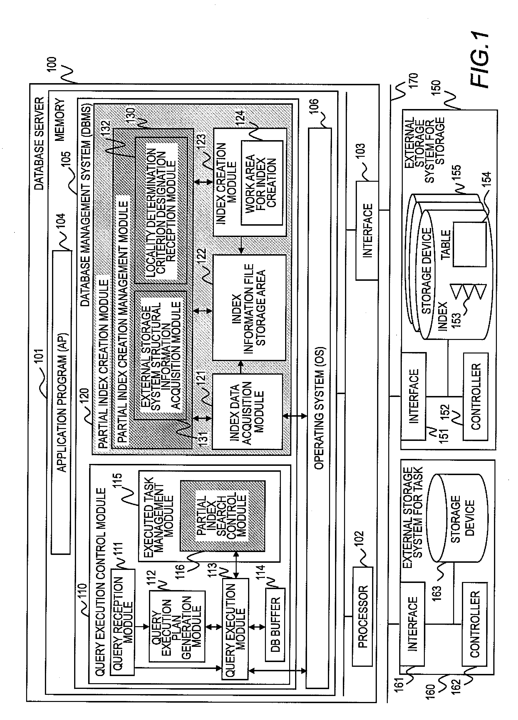
[0048]FIG. 1 is a block diagram illustrating a configuration of a computer system according to a first embodiment of this invention.

[0049]The computer system according to the embodiments of this invention includes a database server 100, an external storage system for storage 150, and an external storage system for task 160. A database management system operates in the database server 100. The external storage system for storage 150 stores data managed by the database management system. The external storage system for task 160 temporarily stores data generated in the course of processings performed by the database management system.

[0050]The database server 100, the external storage system for storage 150, and the external storage system for task 160 are coupled to one another via a network 170. For example, the network 170 is a storage area network (SAN) to which the fibre channel (FC) protocol is applied, but the network 170 may be any other type of network than the above. For exam...

second embodiment

[0125]In the first embodiment of this invention, data pieces of the table 154 are stored in a contiguous storage area. In a second embodiment, in contrast, description is given of a case where data pieces of the table 154 are not stored in the contiguous storage area.

[0126]It should be noted that differences from the first embodiment are mainly described in the second embodiment and subsequent embodiments, and components and processings common to those of the first embodiment are denoted by the same reference symbols, to thereby omit description thereof.

[0127]FIG. 8 is a block diagram illustrating a configuration of a computer system according to the second embodiment of this invention.

[0128]The second embodiment of this invention is different from the first embodiment in the partial index creation module 120. Specifically, the partial index creation module 120 according to the second embodiment includes a disk-based last address storage module 833 in addition to the components of t...

third embodiment

[0154]In a third embodiment of this invention, in addition to the criterion regarding the structural information of the external storage system for storage 150, there is further provided a criterion that the processing of creating a partial index can be executed on the memory of the computer to determine locality. With this configuration, the external storage system for task 160 does not need to be accessed at the time of index creation, and accordingly, the index creation time period can be shortened.

[0155]A computer system according to the third embodiment of this invention has a configuration obtained by excluding the external storage system for task 160 from the configuration of the computer system according to the first embodiment. It should be noted that it is at the time of index creation that the external storage system for task 160 is unnecessary. Hence, in a case where the external storage system for task 160 is assumed to be necessary at the time of search execution or ot...


PUM


Abstract

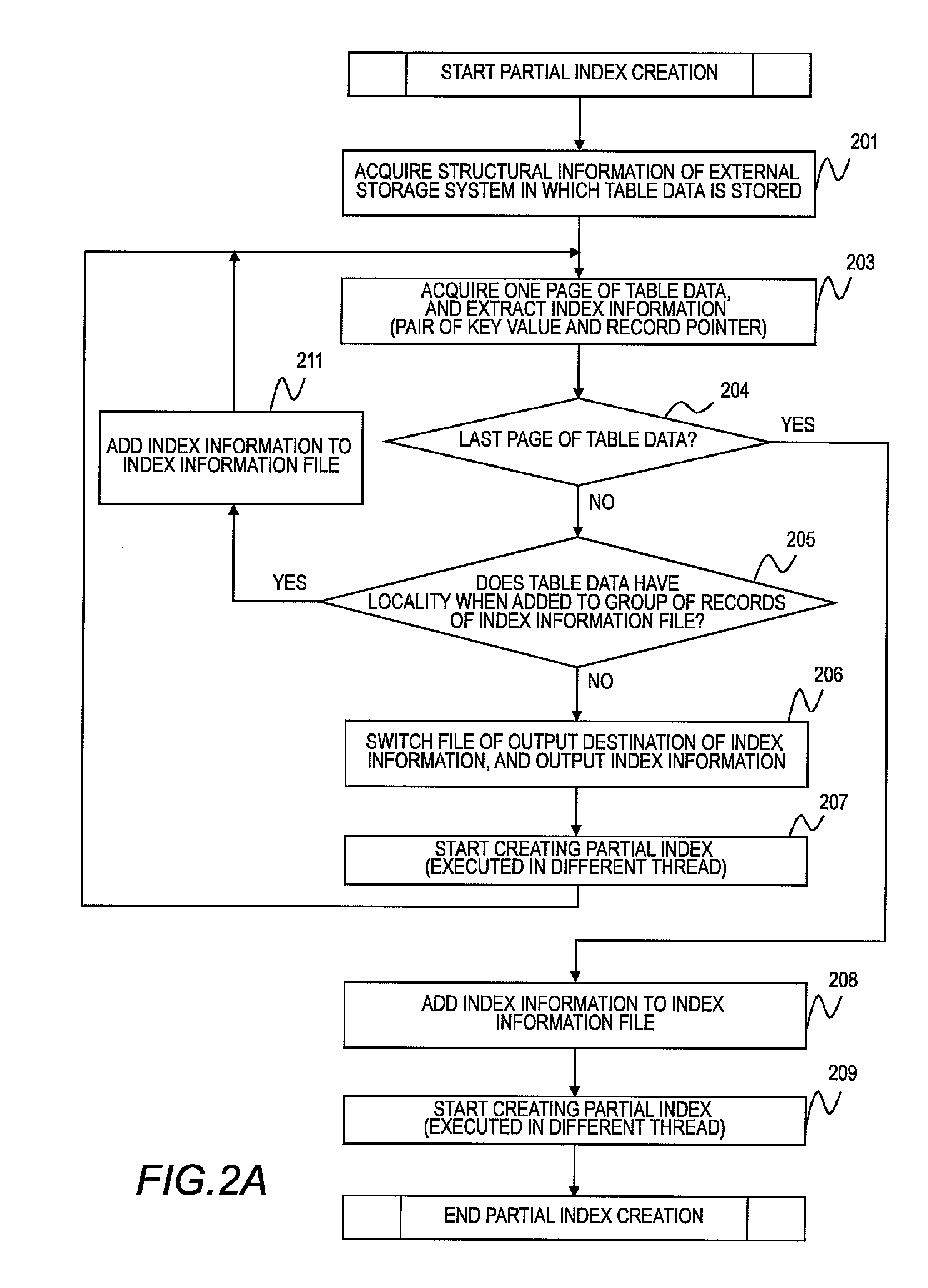
Provided is a database processing system including: a computer for outputting data in response to a received query request; and a storage system including a storage device for storing the data, in which: the storage device stores a plurality of partial indices indicating a storage location of the data; the data stored in the storage device is grouped; and the computer is configured to: receive the query request for the data; acquire one of the plurality of partial indices; specify, based on the query request for the data and the acquired one of the plurality of partial indices, a location at which the requested data is stored; and send a request to acquire the data stored at the specified location to the storage system. Accordingly, in the database processing system, a time period necessary to input and output the data is shortened.

Description

CLAIM OF PRIORITY[0001]The present application claims priority from Japanese patent application JP 2009-116517 filed on May 13, 2009, the content of which is hereby incorporated by reference into this application.BACKGROUND OF THE INVENTION[0002]This invention relates to a technology of processing data managed by a database using an index.[0003]In recent years, introduction of the radio frequency identification (RFID) has rapidly increased the scale of a database for storing data such as transaction data and traceability data. Further, there has increasingly arisen a need to use such a large-scale database for business analysis and sales analysis and to apply results thereof to business. The data size is expected to exceed 100 terabytes, and be on the scale of petabytes.[0004]Business analysis and sales analysis are conducted from various perspectives, and therefore a database processing system is required to process ad hoc queries for large-size data at high speed. JP 2007-34414 A ...

Claims


Application Information

Patent Timeline
IPC IPC(8): G06F17/30
CPCG06F17/30306G06F16/217
Inventor TANAKA, MICHIKOUSHIJIMA, KAZUTOMOSHIMIZU, AKIRATOKUDA, SEISUKEFUJIWARA, SHINJIKAWAMURA, NOBUO
Owner HITACHI LTD
Learn More