KVM switching device, sever rack assembly and sliding mechanism thereof

Inactive Publication Date: 2009-12-15
ATEN INT CO
View PDF5 Cites 32 Cited by
  • Summary
  • Abstract
  • Description
  • Claims
  • Application Information

AI Technical Summary

Benefits of technology

[0002]The invention relates in general to KVM (keyboard-video-mouse) switch devices and in particular to a KVM switch device having a sliding mechanism.

Problems solved by technology

However, due to the height constraints on the 1U server rack, the dimensions of the keyboard and the display have to fulfill the dimension limitations to operate on the server rack.

Method used


Image

  • KVM switching device, sever rack assembly and sliding mechanism thereof
  • KVM switching device, sever rack assembly and sliding mechanism thereof
  • KVM switching device, sever rack assembly and sliding mechanism thereof

Examples


Embodiment Construction

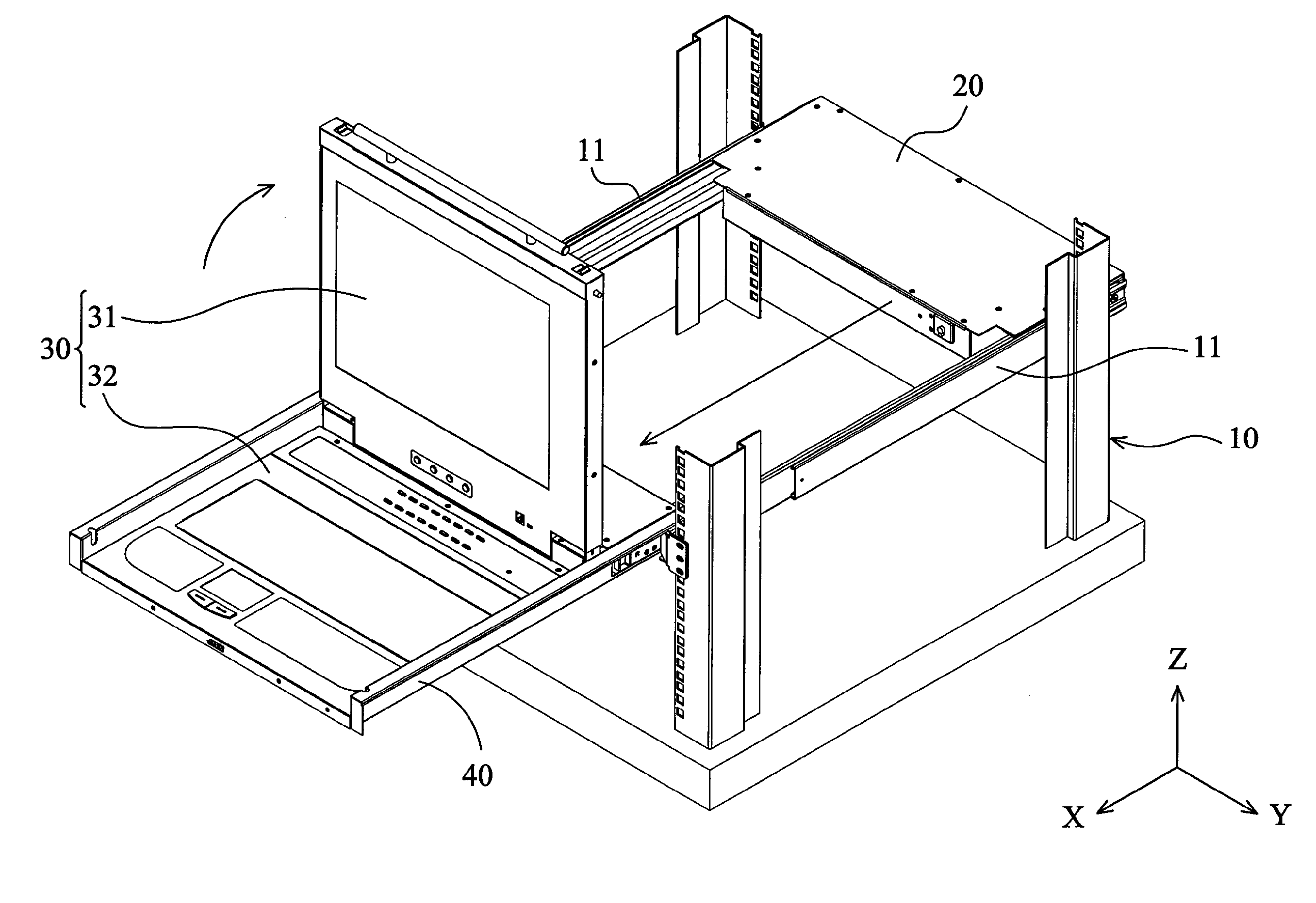
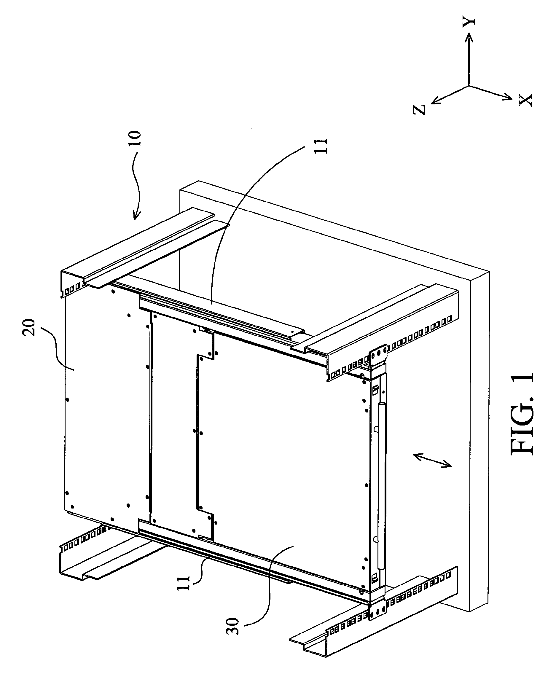
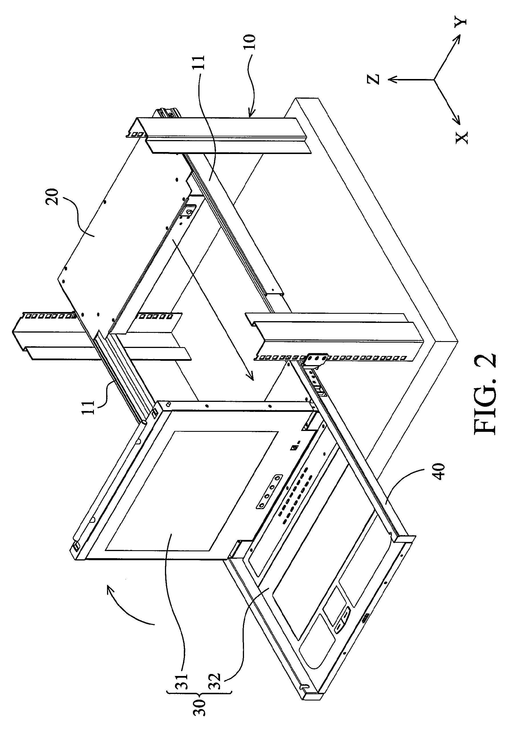
[0017]Referring to FIGS. 1 and 2, an embodiment of a KVM switch device primarily comprises a server rack 10, two longitudinal frames 11 mounted on the server rack 10, a switch part 20 connected to the frames 11, and a console unit 30 movable along the X axis between a closed position (FIG. 1) and an open position (FIG. 2) with respect to the frames 11. Here, the switch part 20 and the console unit 30 are electrically communicated with each other via flexible cables (not shown) for controlling different servers.

[0018]As shown in FIGS. 2 and 3, the console unit 30 is held by a bracket 40, wherein the bracket 40 is movably connected to the frames 11 via a sliding mechanism (discussed subsequently in connection with FIGS. 3, 4A and 4B as item 50). In this embodiment, the console unit 30 includes a display part 31 and an input part 32 having a keyboard and a pointing device, wherein the display part 31 is pivotally connected to the input part 32. When using the KVM switch device, the con...


PUM


Abstract

A KVM switch device is provided. The KVM switch device comprises a frame, a switch part fixed to the frame, a console unit movably connected to the switch part, and a sliding mechanism disposed between the console unit and the frame, wherein the switch part communicates with the console unit. The sliding mechanism comprises at least one guide rod disposed on the frame and at least one sliding bearing sliding along the guide rod. The console unit is movable between a closed position and an open position by the sliding bearing sliding along the guide rod.

Description

BACKGROUND OF THE INVENTION[0001]1. Field of the Invention[0002]The invention relates in general to KVM (keyboard-video-mouse) switch devices and in particular to a KVM switch device having a sliding mechanism.[0003]2. Description of the Related Art[0004]Conventional 1U computer servers assembled on a standard 1U server rack is an industry standard arrangement. Each slot of the server rack is about 1.75 inches (about 4.5 centimeters), so that the 1U server and the server rack effectively conserve the space occupied by the computer servers. Moreover, the 1U servers and racks are more efficiently controlled because the 1U servers and racks can be centrally managed and easily stacked.[0005]To conveniently control the stacked 1U computer servers on the server rack, KVM (keyboard-video-mouse) switches are usually used to connect and control the computer servers. Hence, the quantity of the displays and keyboards for controlling the computer servers can be effectively reduced and occupied ...

Claims


Application Information

Patent Timeline
Patent Type & Authority Patents(United States)
IPC IPC(8): H05K5/00A47B88/00H05K7/00H05K7/16
CPCG06F1/182
Inventor WU, SUI-ANLEE, LING-WEI
Owner ATEN INT CO
Why Eureka
Try Eureka