Pneumatic tire with tread including sipes having bent portions formed with zigzag shape with amplitude in radial direction

a technology of pneumatic tires and sipes, which is applied in the field of pneumatic tires, can solve the problems of reduced block stiffness, reduced ground contact area of tires, and deterioration of tire performance both during summer and winter, and achieve excellent traveling performance and avoid failure of mold releas

Active Publication Date: 2009-12-29
THE YOKOHAMA RUBBER CO LTD
View PDF18 Cites 6 Cited by
  • Summary
  • Abstract
  • Description
  • Claims
  • Application Information

AI Technical Summary

Benefits of technology

[0009]An object of the present invention is to provide a pneumatic tire which is allowed, depending on a shape of sipes, to increase block stiffness not only during braking and driving but also during cornering, and is allowed thereby to compatibly enhance tire performances both during braking and driving and during cornering.

Problems solved by technology

However, in the case where tread rubber is reduced in hardness, block stiffness is reduced.
This causes the block to fall down during braking and driving and during cornering, and hence leads to reduction in ground contact area of the tire, and as a result, tire performances both during summer and during winter are deteriorated.
In this case, although it is possible to increase block stiffness during braking and driving, there is a disadvantage that an effect of increasing block stiffness during cornering can be scarcely obtained.
In this case, although it is possible to expect an effect of increasing block stiffness during cornering, there is a disadvantage that a place where it can be arranged is limited because the sipe has a direction.
In this case as well, there is a disadvantage that block stiffness during cornering is low as compared to block stiffness during braking and driving.

Method used


Image

  • Pneumatic tire with tread including sipes having bent portions formed with zigzag shape with amplitude in radial direction
  • Pneumatic tire with tread including sipes having bent portions formed with zigzag shape with amplitude in radial direction
  • Pneumatic tire with tread including sipes having bent portions formed with zigzag shape with amplitude in radial direction

Examples


examples

[0066]First, tires for Conventional Examples 1 to 3 and Example 1 were prepared as icy and snowy road pneumatic tires each of which had a tire size of 195 / 65R15 91Q and a block pattern, and which were made variously different only in shape of the sipes provided in the block.

[0067]Conventional Example 1 is the one, as described in Japanese patent application Kokai publication No. 2000-6619, adopting sipes each of which forms a zigzag shape on a tread surface of the tire, and has amplitudes of zigzag shapes varied inside the block (refer to FIG. 12). Conventional Example 2 is the one, as described in Japanese patent application Kokai publication No. 2002-301910, adopting sipes each of which forms a zigzag shape on a tread surface of the tire, and has triangular pyramids and inverted triangular pyramids alternately arranged inside the block (refer to FIG. 13). Conventional Example 3 is the one, as described in Japanese patent application Kokai publication No. 2002-321509, adopting sipe...


PUM


Abstract

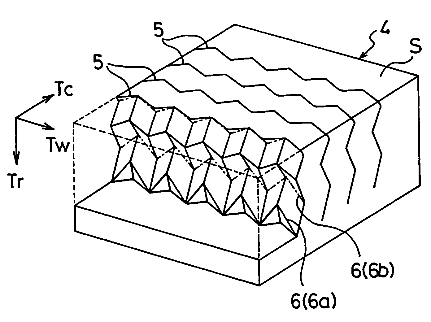
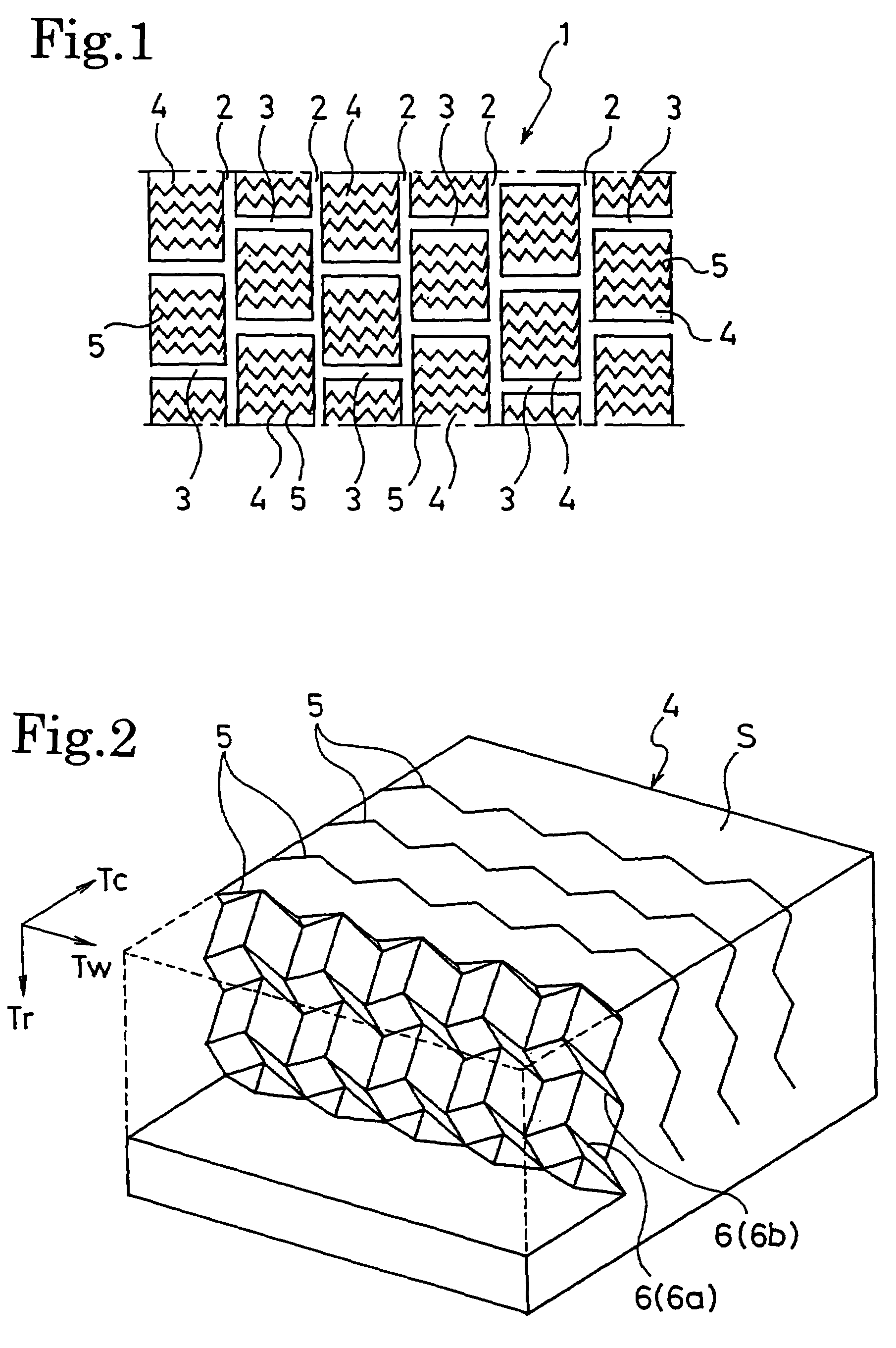
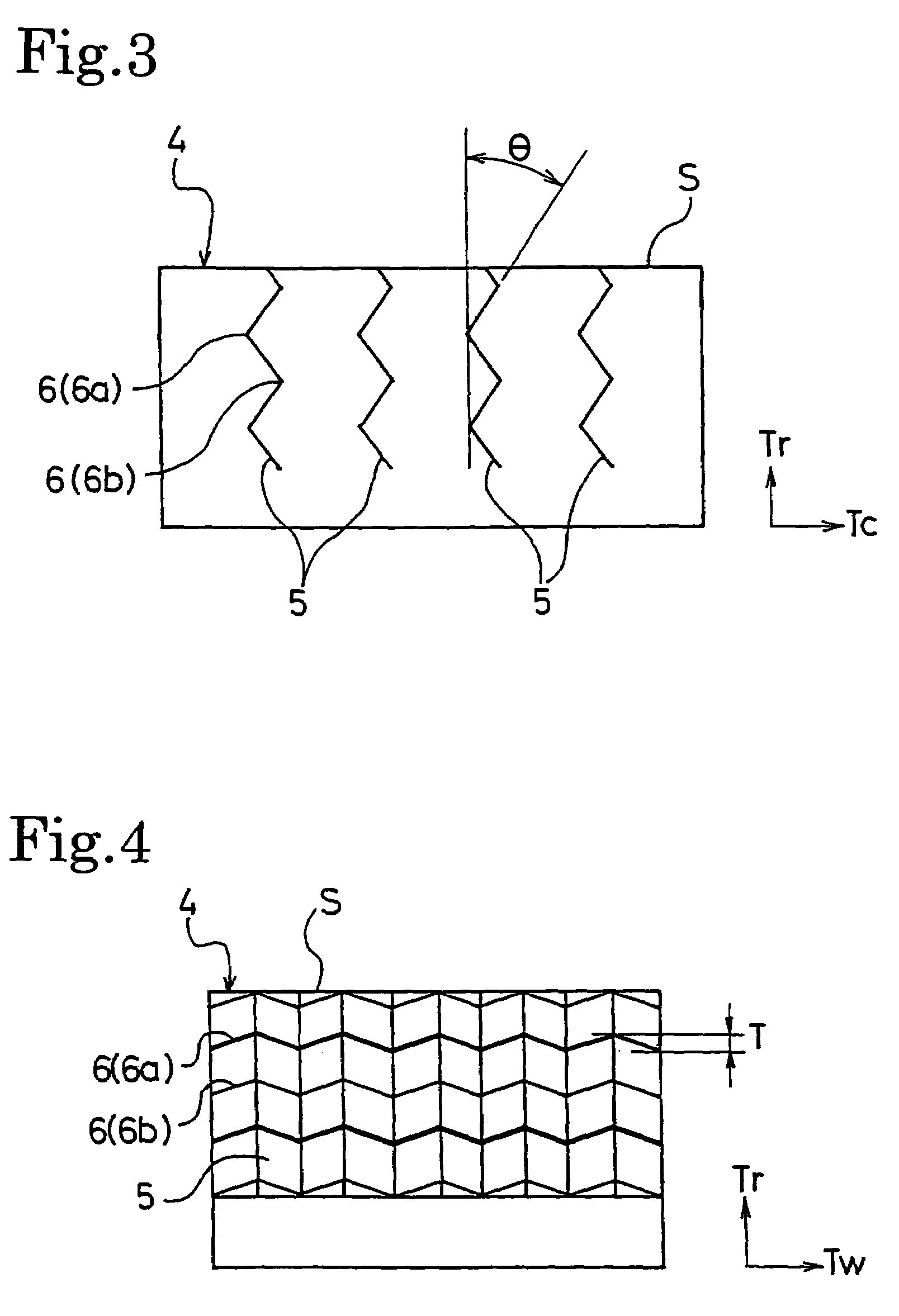
Disclosed is a pneumatic tire which is allowed to increase block stiffness not only during braking and driving but also during cornering, and is allowed thereby to compatibly enhance tire performances both during braking and driving and during cornering. The pneumatic tire of the present invention is one where a plurality of longitudinal grooves extending in a tire circumferential direction and a plurality of lateral grooves extending in a tire widthwise direction are provided in a tread portion, a plurality of blocks are defined by these longitudinal and lateral grooves, and a plurality of sipes extending in the tire widthwise direction are provided to each of the blocks, wherein, with regard to each of the sipes, a zigzag shape is formed on a tread surface, bent portions ranging in the tire widthwise direction while bent in the tire circumferential direction are formed inside the block at at least two positions in the tire radial direction, and a zigzag shape with an amplitude in the tire radial direction is formed in each of the bent portions.

Description

TECHNICAL FIELD[0001]The present invention relates to a pneumatic tire where a plurality of sipes are provided in a block, and more specifically, relates to a pneumatic tire which is allowed, by shapes of the sipes, to increase block stiffness not only during braking and driving but also during cornering, and is allowed thereby to compatibly enhance tire performances both during braking and driving and during cornering.BACKGROUND ART[0002]In an icy and snowy road pneumatic tire, as improving measures for on-ice performances, increasing an edge amount of sipes provided in a block thereof, reducing hardness of tread rubber, and the like have been generally attempted. However, in the case where tread rubber is reduced in hardness, block stiffness is reduced. This causes the block to fall down during braking and driving and during cornering, and hence leads to reduction in ground contact area of the tire, and as a result, tire performances both during summer and during winter are deteri...

Claims


Application Information

Patent Timeline
Patent Type & Authority Patents(United States)
IPC IPC(8): B60C11/12
CPCB60C11/12B60C11/125B60C11/1218B60C2011/1213Y10S152/03Y10S152/902
Inventor HASHIMOTO, YOSHIMASAKISHIZOE, ISAMU
Owner THE YOKOHAMA RUBBER CO LTD
Why Eureka
Try Eureka