Prosthetic locking device

a technology of locking device and prosthesis, which is applied in the field of prosthetic locking device, can solve the problems of not being able to adjust the volume of the residual limb without manual adjustment, the design is fraught with practical difficulties, and cannot be fully solved, so as to reduce the concern of rusting or corroding of the lock, and the effect of oxidation resistan

Inactive Publication Date: 2009-12-29
FILLAUER LLC
View PDF3 Cites 6 Cited by
  • Summary
  • Abstract
  • Description
  • Claims
  • Application Information

AI Technical Summary

Benefits of technology

[0013]Another significant advantage of the invention, not addressed by the prior art, is that the moving components, which include the plunger and rolling elements, can be made of softer materials, which are more resistant to oxidation in wet or humid environments. Examples of suitable materials include but are not limited to austenitic stainless steel, titanium, and brass. This feature will allow the amputee to use the locking device in aquatic sports with less concern of the lock rusting or corroding.
, not addressed by the prior art, is that the moving components, which include the plunger and rolling elements, can be made of softer materials, which are more resistant to oxidation in wet or humid environments. Examples of suitable materials include but are not limited to austenitic stainless steel, titanium, and brass. This feature will allow the amputee to use the locking device in aquatic sports with less concern of the lock rusting or corroding.

Problems solved by technology

This design was fraught with practical difficulties, but for many years was the only design available.
Despite the improvements that the smooth pin lock system offers, it has not been a complete solution and has introduced its own disadvantages.
All of the automatic locking mechanical connectors (ratcheting shuttle, gear driven clutch, and smooth pin) have the drawback of requiring the plunger and the lock to be aligned on the same axis.
The lanyard and shuttle lock systems do not automatically lock and cannot accommodate volume changes in the residual limb without manual adjustments.
Limb shrinkage loosens the fit in the socket and causes the residual limb to slip deeper into the prosthesis.
The ratcheting shuttle lock also suffers from this drawback because the discrete locking steps are spaced too widely to make fine adjustments.
As components wear, the retention of the prosthesis becomes less secure.
Over time, the limited surface area of the washer becomes worn, introducing unwanted play or backlash into the locking mechanism.
An additional drawback to the washer design is that it is incapable of accepting flexible plungers because the angle generated by the washer is insufficient to prevent a flexible plunger from snaking out of the lock housing.
When the lock is manufactured with less than perfect alignment in the socket the washer is subject to extraordinary wear causing the locking mechanism to fail prematurely.
A further drawback common to all the mechanical connectors is that they are necessarily manufactured with materials that can withstand the rigors of the locking mechanism.
Such steel bearing grade parts, however, are highly subject to corrosion, particularly when the prosthesis is used in environments offering exposure to liquids or other contaminants.
Internal corrosion of the locking device can lead to seizure and failure of the moveable components.
Efforts to overcome the corrosion problem by forming the moving components of a corrosion resistant metal alloy, such as austenitic stainless steel (type 300 series) typically are not practical since such corrosion resistant steel cannot be hardened to the extent necessary for satisfactory life of the moving components.
However, the corrosion resistance is less than that of the 300 series stainless steels.
The result is that neither grade of stainless is suitable for the current lock designs.
Therefore, amputees that live active lifestyles, who are prone to get their prosthesis wet are forced to live with locking mechanisms that corrode or fail to operate with peak efficiency.

Method used


Image

  • Prosthetic locking device
  • Prosthetic locking device
  • Prosthetic locking device

Examples


Embodiment Construction

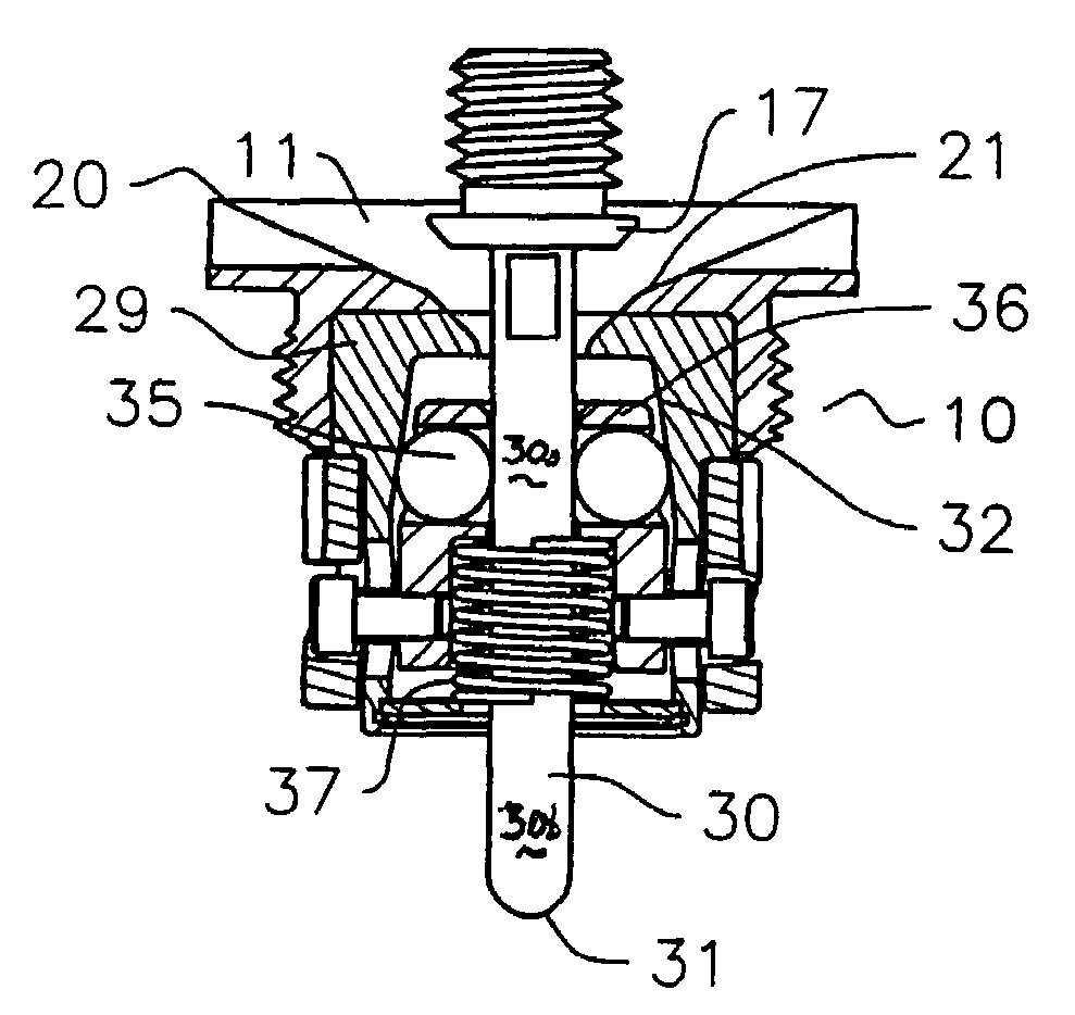
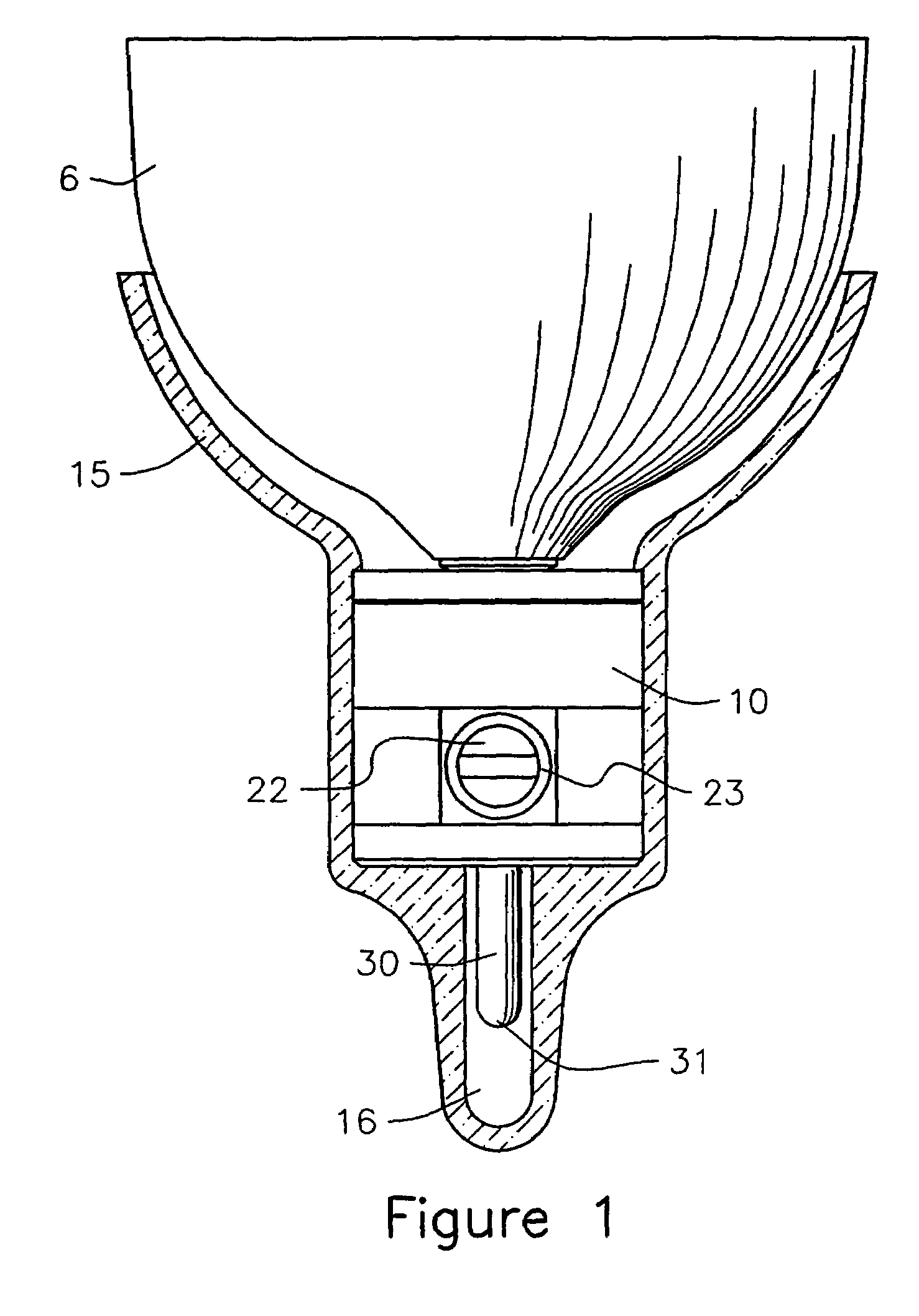
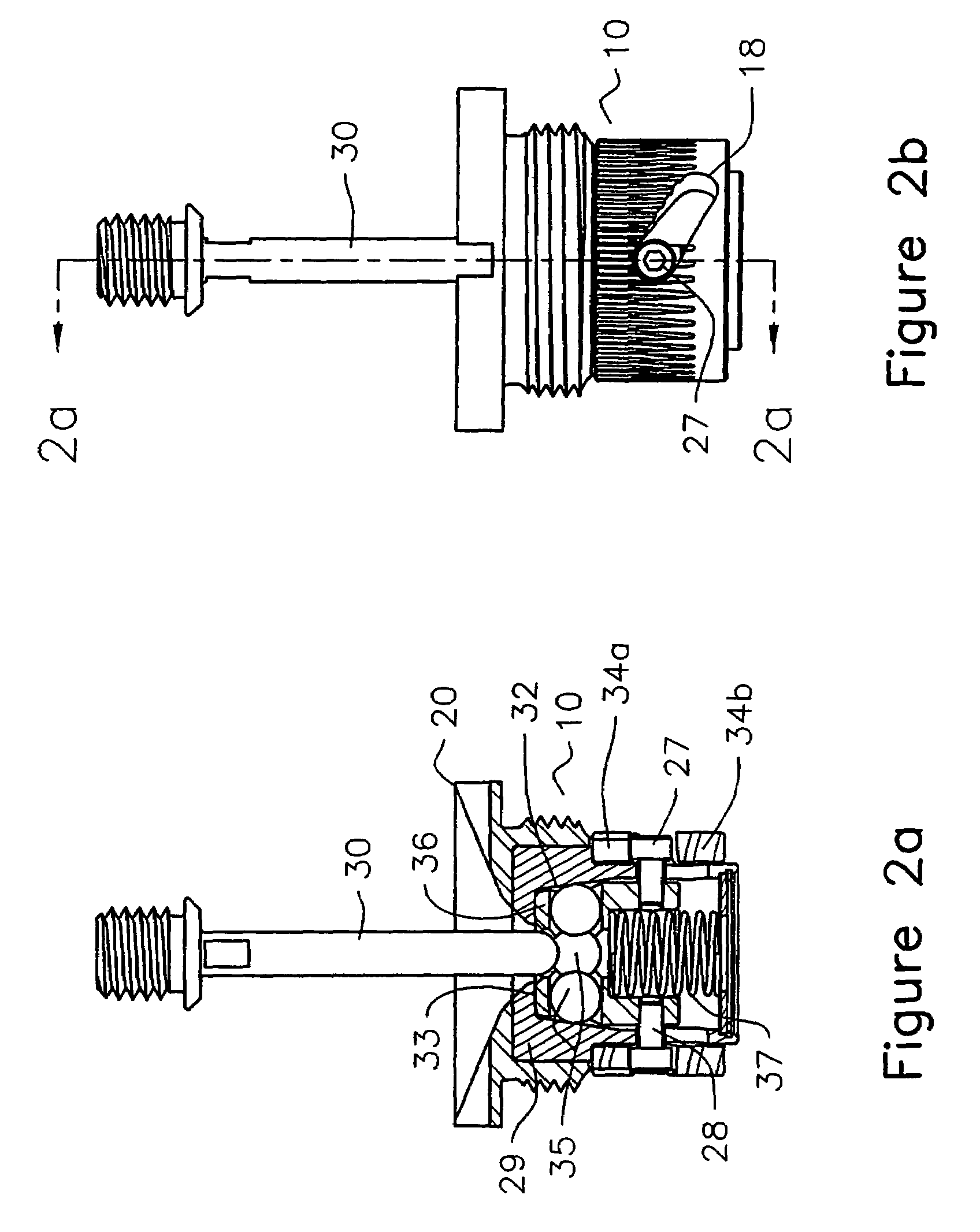
[0025]Referring now to the drawings and in particular to FIG. 1, a cross-sectional view of a prosthetic socket 15 with a smooth plunger 30 engaged in a locking device 10 is shown. The plunger 30 is attached to the distal end of a sleeve 6 adapted to fit over the residual limb of an amputee. Typical sleeve materials are urethanes, thermoplastic elastomers, or silicone based polymers. The socket 15 and locking device 10 are secured to the proximal end of a prosthesis, typically a prosthetic limb. The plunger 30 is shown fully engaged within the locking device 10. The distal end 31 of the plunger has passed through the locking device 10 and occupies the prosthetic socket plunger cavity 16. The plunger 30 may be tubular or rigid as depicted in FIG. 2a, or flexible such as the braided or twisted cable depicted in FIG. 6.

[0026]In a preferred embodiment the plunger 30 should be substantially smooth along its length, however, as in the case of braided cable, ridges in and around the circumf...


PUM


Abstract

A device is provided to lock the residual limb of an amputee into a prosthesis. The device is comprised of rolling elements within a tapered housing which accepts a smooth plunger, such as a wire, cable, or rod connected to a suspension sleeve, with minimal resistance while opposing removal of the plunger from the locking device until the rolling elements have been retracted with a release mechanism. The nature of this device allows it to compensate for irregularities or wear in the plunger while continuing to securely lock the prosthesis to the sleeve. This locking device will function properly with a certain amount of misalignment between the lock and the plunger.

Description

RELATED APPLICATIONS[0001]The present application is a continuation of U.S. Ser. No. 10 / 121,196 filed Apr. 12, 2002 which is being allowed to become abandoned.FIELD OF THE INVENTION[0002]The present invention is an improved locking device for attaching a prosthesis to a suspension sleeve on a residual limb.BACKGROUND OF THE INVENTION[0003]Various methods of attaching a prosthesis to an amputee's residual limb have been utilized over the years. Despite advances in materials and design many of the older methods are still being used. The earliest methods were strap and belt type suspension systems. In this design, the amputee inserted the residual limb into the prosthesis and tightened a belt, typically made from leather, to hold the prosthesis to the limb. This design was fraught with practical difficulties, but for many years was the only design available. A second-generation design improvement uses flexible inner integral suction suspension sockets. These designs are especially usef...

Claims


Application Information

Patent Timeline
Patent Type & Authority Patents(United States)
IPC IPC(8): A61F2/80A61F2/00A61F2/50A61F2/78
CPCA61F2/78A61F2/80A61F2002/3038A61F2002/30504A61F2220/0033A61F2002/5073A61F2002/7875A61F2220/0025A61F2002/5067A61F2002/30331A61F2002/305
Inventor COOP, BRIAN T.
Owner FILLAUER LLC
Why Eureka
Try Eureka