Brake assembly

Active Publication Date: 2010-01-05
GOODRICH CONTROL SYST LTD
View PDF14 Cites 4 Cited by
  • Summary
  • Abstract
  • Description
  • Claims
  • Application Information

AI Technical Summary

Benefits of technology

[0022]By manufacturing the module relatively accurately, the brake elements can be replaced by replacing the module

Problems solved by technology

However, in aerospace applications, where component weight and size are of great importance, the numb

Method used


Image

  • Brake assembly
  • Brake assembly
  • Brake assembly

Examples


Embodiment Construction

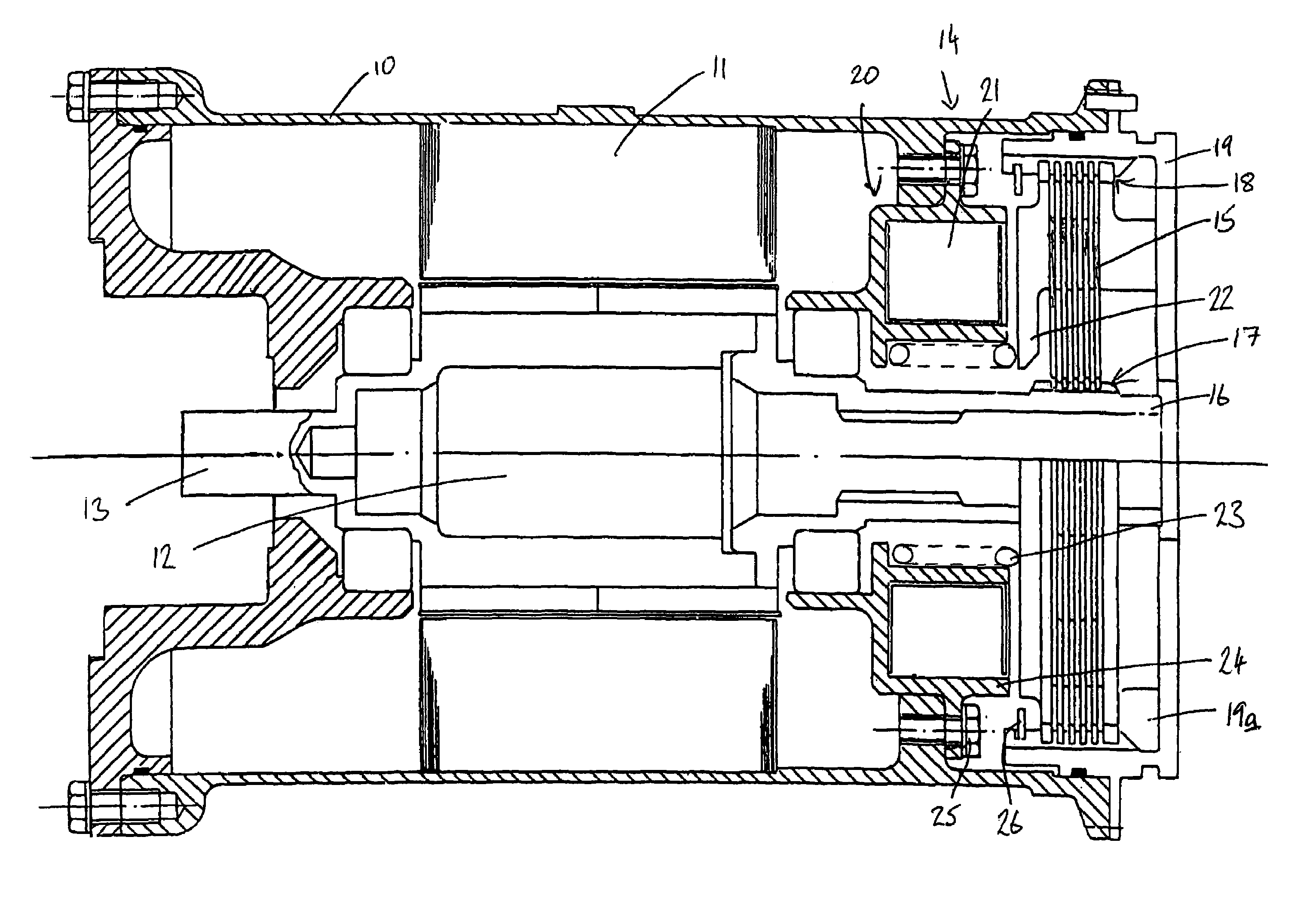
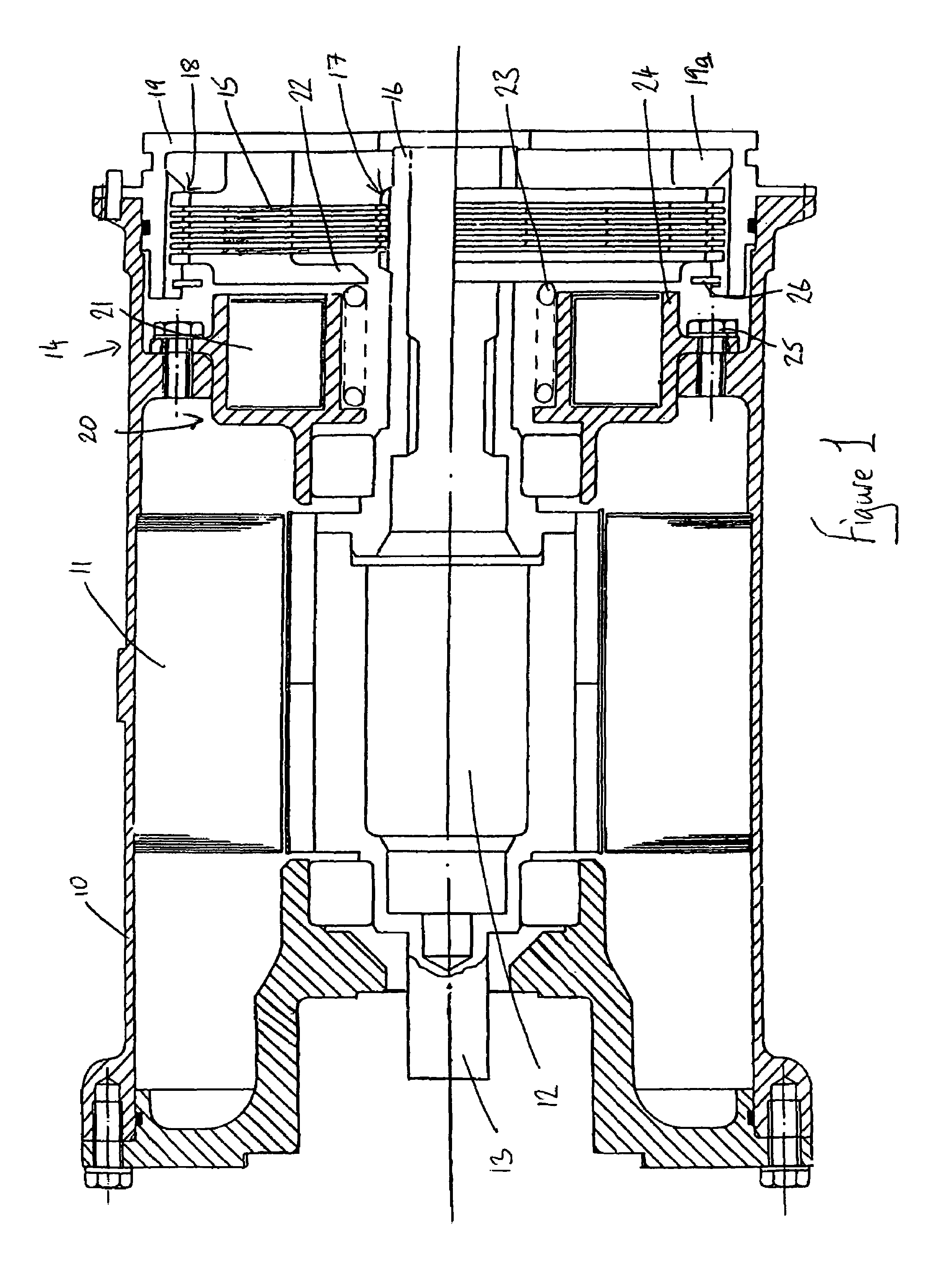
[0027]FIG. 1 illustrates a motor which comprises a housing 10 within which a stator 11 is mounted. A rotor 12 is rotatable under the influence of a magnetic field generated, in use, by the stator. The rotor 12 includes an output shaft 13 which projects from an end of the housing 10 which, in use, is coupled through a suitable gearing arrangement to an input of a device to be operated by the motor. The device may, for example, take the form of a rotary actuator which is used to drive a hatch or door of an aircraft between a closed position and an open position. As described hereinbefore, there may be a requirement for the door to move between its fully closed position and its fully open position within a short period of time, and hence the motor must be capable of operating at a high speed. For example, the motor may be intended to operate at a speed of the order of 15,000 rpm through a high ratio gearbox. The motor may typically have an output power in excess of 25 kW. It will be ap...


PUM

PropertyMeasurementUnit
Temperatureaaaaaaaaaa
Thicknessaaaaaaaaaa
Thicknessaaaaaaaaaa

Abstract

A brake assembly for a motor, the brake assembly comprising a stack of brake elements, at least one of which is rotatable with an output shaft of the motor, in use, and at least one of which is non-rotatable relative to a housing, and actuator means controlling the magnitude of a compressive load applied to the brake elements, wherein the brake elements are provided, at least in part, with a surface coating which raises the coefficient of friction of the brake elements to a value greater than 0.2. The invention also relates to a brake assembly comprising a plurality of brake elements and an electromagnetic actuator arranged to permit control of a compressive load applied to the brake elements, wherein the actuator includes a winding located such that the brake elements are accessible without requiring removal of the winding from the motor.

Description

TECHNICAL FIELD[0001]This invention relates to a brake assembly. The invention is particularly suitable for use with an electric motor to slow or stop the motor or to hold the motor in a selected position, and is suitable for use in aerospace applications.BACKGROUND OF THE INVENTION[0002]Electric motors are used in a range of aerospace applications, for example to drive hatches or doors between their open and closed positions or to drive flaps or the like. In some applications, where rapid movement is to be achieved, the motor must be able to rotate at very high speeds. It is important, in such applications, to provide a brake assembly to permit rapid deceleration of the motor to avoid damage to the aircraft when the hatch, door, flap or other component approaches the end of its range of movement, or to stop the component in a desired location. Additionally, the brake assembly may be required to operate as a primary or secondary holding means to prevent movement of, for example, the...

Claims


Application Information

Patent Timeline
IPC IPC(8): B60L7/00F16D55/36F16D65/12F16D65/14H02K7/102
CPCF16D55/36F16D65/12H02K7/1025F16D2065/132F16D2121/22F16D2250/0046F16D2250/0084
Inventor HAYWARD, DENNIS RICHARDHARRIS, PAULBONNIEMANN, DAVID
Owner GOODRICH CONTROL SYST LTD
Why Eureka
Try Eureka