Shield Member in LED Apparatus

Active Publication Date: 2008-11-06
IDEAL IND LIGHTING LLC
View PDF36 Cites 14 Cited by
  • Summary
  • Abstract
  • Description
  • Claims
  • Application Information

AI Technical Summary

Benefits of technology

[0008]Another object of this invention is to provide LED lighting apparatus with directional shielding which by its nature facilitates accurate manufacture, including of multi-LED fixtures.
[0009]Another object of this invention is to provide LED lighting apparatus with directional shielding having the above advantages and with improved effectiveness in light distribution, including avoidance of light distribution to a non-preferential side.
[0010]Another o

Problems solved by technology

Satisfying such concerns can be difficult when LEDs are used as light sources, parti

Method used


Image

  • Shield Member in LED Apparatus
  • Shield Member in LED Apparatus
  • Shield Member in LED Apparatus

Examples


Example

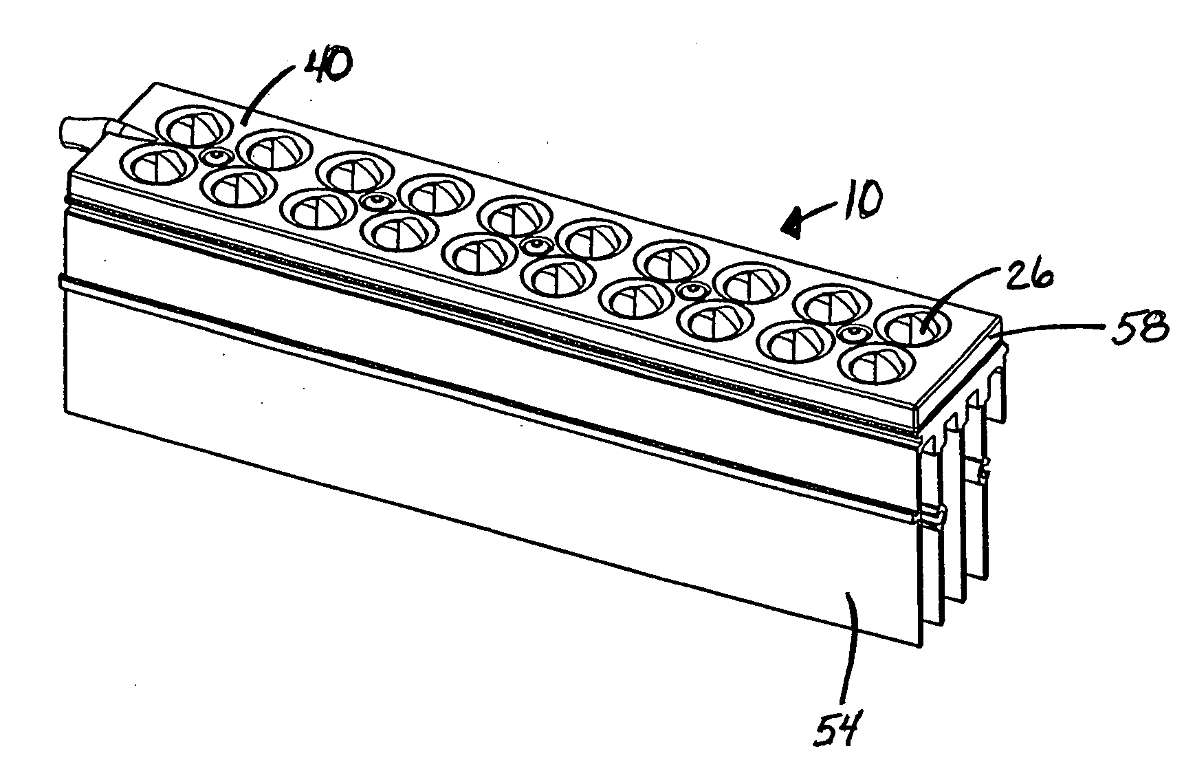
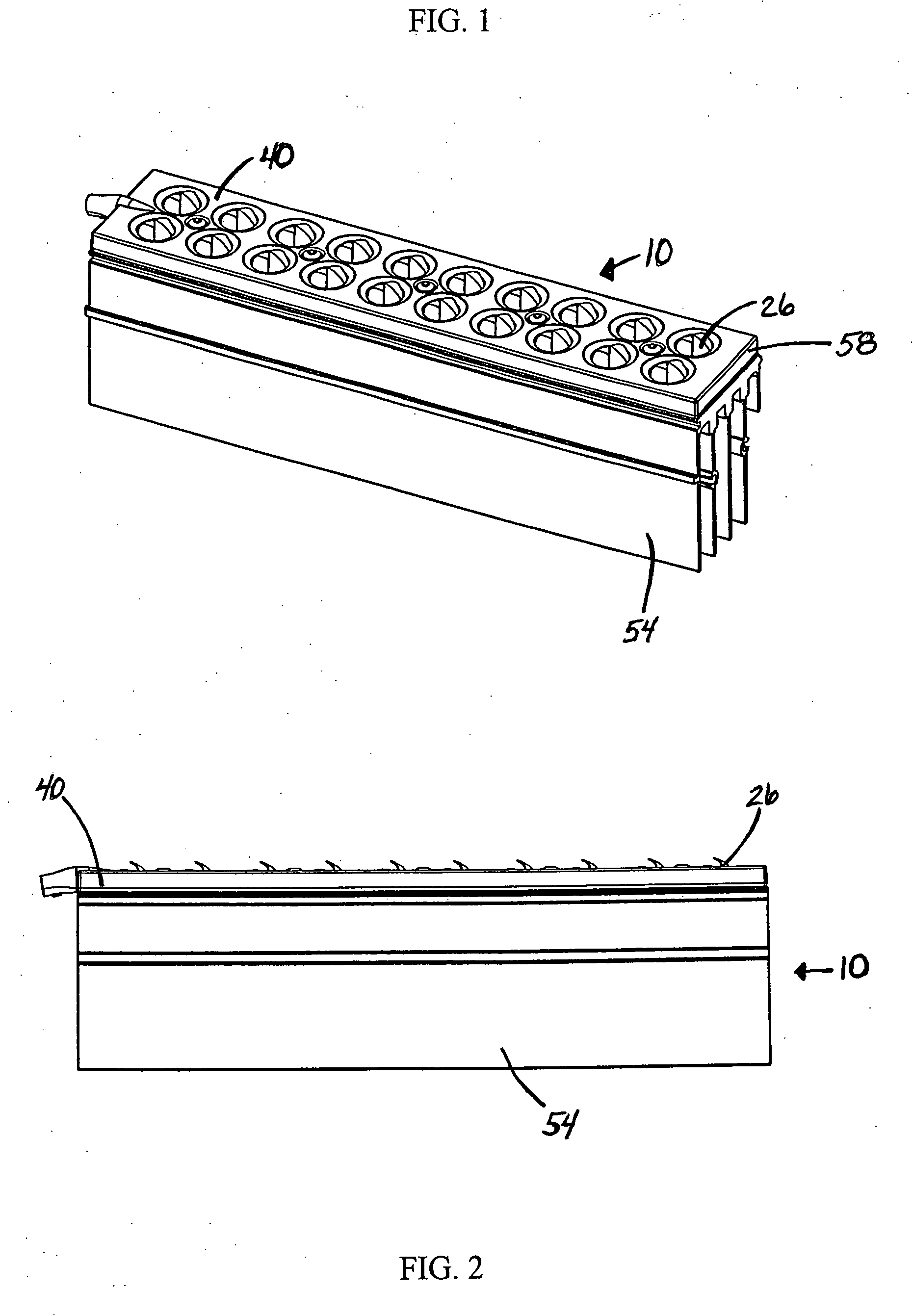
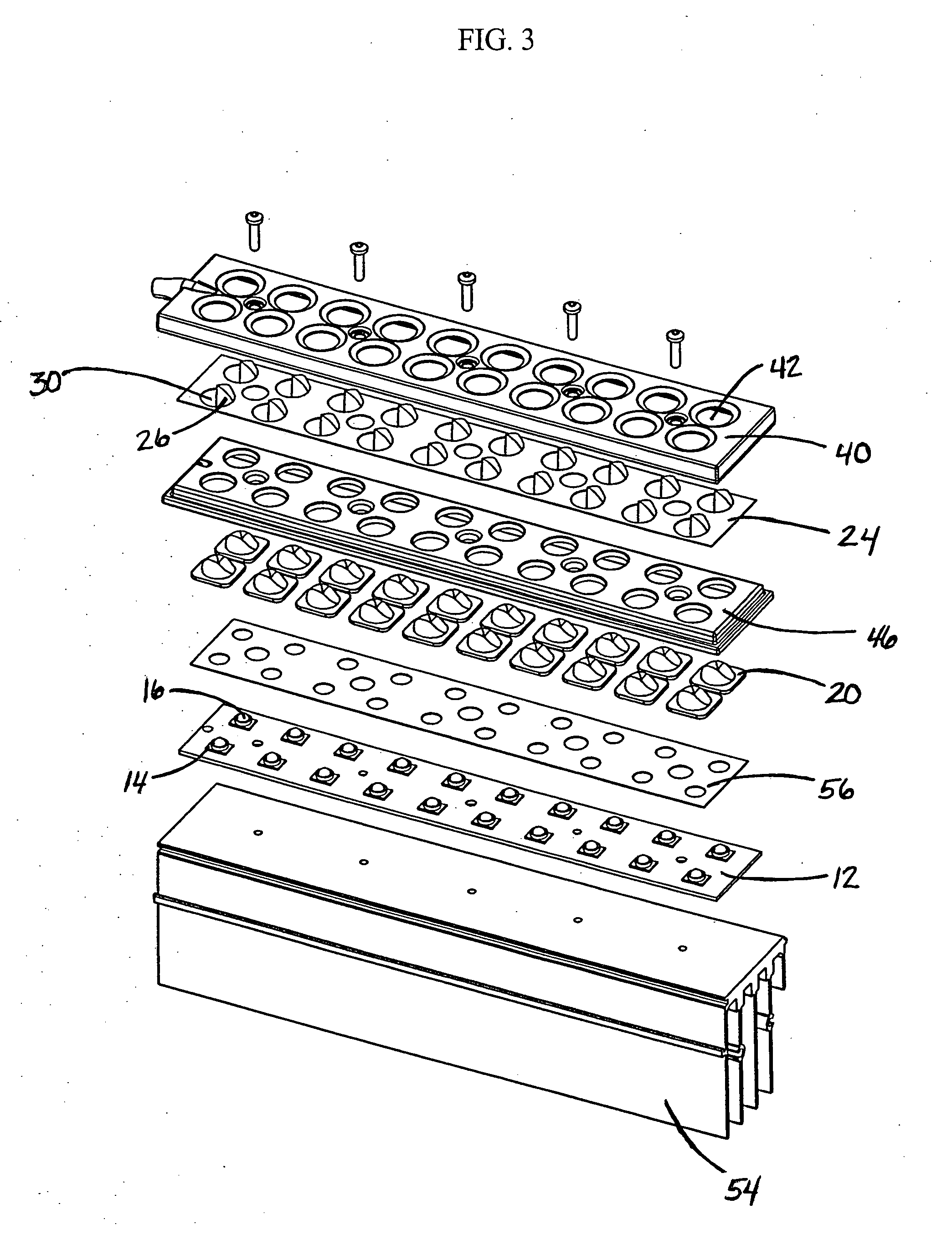
[0034]FIGS. 1-4 and 9 illustrate an LED apparatus 10 for illumination toward a preferential side 36 in a downward direction 48 and outward direction 49. LED apparatus 10 includes a mounting board 12, LED package 14 thereon with primary lens 16 having central axis 18, and secondary lens member 20 over primary lens 16 and establishing light path 22 therebetween. The mounting board 12 is connected to a heat sink 54 as shown in FIGS. 1 and 2. One or more, typically several, LED packages 14 are arranged on a mounting board 12 to form what is referred to as an LED module 58. One or more LED modules 58 are used as the light source for various innovative lighting fixtures.

[0035]As shown in FIG. 3 shield member 24, in the form of a layer, is positioned over mounting board 12, LED package 14 and secondary lens member 20. Shield member 24 has shield portion 26 and a substantially planar non-shield portion 28 thereabout as seen in FIG. 6. FIGS. 5 and 6 illustrate that shield member 24 has a shi...


PUM


Abstract

An LED apparatus for illumination toward a preferential side in a downward and outward direction including a shield member in the form of a layer positioned over LED packages and secondary lens members. The shield member has a shield portion and a substantially planar non-shield portion thereabout. In preferred embodiments, the shield portion extends over a part of the lens portion of the secondary lens member. A cover preferably secures the shield member with respect to the secondary lens member, the primary lens and the LED package, the shield member preferably being sandwiched between the cover and the flange of the secondary lens member.

Description

FIELD OF THE INVENTION[0001]The invention relates generally to the field of lighting systems and, more particularly, to apparatus for utilizing LED (light-emitting diode) sources for illuminating areas with a predefined pattern of light intensity toward a preferential side.[0002]BACKGROUND OF THE INVENTION[0003]There is a continuing need for lighting apparatus which is low-cost and energy efficient. LEDs provide light sources which are energy efficient, and advances in LED technology are providing even greater such efficiencies over time. One advantage of using LEDs as light sources is simply that the smaller size of such sources translate into lower material usage within fixtures containing such sources, thus yielding the attendant cost-efficiency.[0004]Preferred performance requirements for lighting systems for various uses involve freedom of “light spillage” into areas not intended to be lit. For example, it is preferred that roadway and parking lot lighting systems have excellen...

Claims


Application Information

Patent Timeline
IPC IPC(8): H01L33/00
CPCF21S8/08F21S8/086F21V5/04F21V11/16G02B19/0028F21W2131/103F21Y2101/02G02B19/0066F21V13/02F21S8/00F21V5/008F21V19/001F21Y2105/10F21Y2115/10
Inventor WILCOX, KURT S.
Owner IDEAL IND LIGHTING LLC
Why Eureka
Try Eureka