Method of setting the pre-load for a ball socket joint

a pre-load and ball socket technology, applied in the direction of suspensions, couplings, manufacturing tools, etc., to achieve the effect of reducing the compression load within the sock

Active Publication Date: 2010-01-12
FEDERAL MOGUL WORLD WIDE LLC
View PDF92 Cites 31 Cited by
  • Summary
  • Abstract
  • Description
  • Claims
  • Application Information

AI Technical Summary

Benefits of technology

[0008]The subject invention provides a method for positioning and locking the outer bearing in position while the ideal compression is maintained. The subject invention is particularly advantageous in ball and socket type assemblies in which the pre-load compression and clearance is particularly sensitive. Such sensitivity arises in certain all metal component designs, but may also be an issue in some hybrid assemblies which may include non-metal bearing members as well.
[0009]According to another aspect of the invention, a method is provided for assembling an all-metal ball-and-socket type mechanism with a permanent pre-load compression between its articulating components. This method comprises the steps of: providing a metal housing, a metal resilient preload member, and metallic inner bearing having a wear surface, an articulating metal ball stud, and a metallic outer bearing having a wear surface; placing into the housing the resilient preload member, the inner bearing against the resilient preload member, the ball stud in sliding contact with the wear surface of the inner bearing, and the outer bearing with its wear surface in sliding contact with the ball stud; compressing the outer bearing, ball stud and inner bearing as a unit against the resilient preload member until an over-load compression condition or state is reached; reducing the compression load within the socket until an ideal compression condition is achieved between the outer bearing, ball stud and inner bearing; maintaining the ideal compression condition while simultaneously deforming the housing into the outer bearing so as to fix the outer bearing position in the housing and thereby capture the ideal compression condition within the all metal ball and socket mechanism. In a further aspect, the method may include a step of re-forming an up-standing edge of the housing to further effect a fixation of the bearing and the socket preload after the step of deforming the housing into the outer bearing. Alternatively, compressing the socket to an optimal preload without first overloading is an acceptable method of setting the socket preload.

Problems solved by technology

Such sensitivity arises in certain all metal component designs, but may also be an issue in some hybrid assemblies which may include non-metal bearing members as well.

Method used


Image

  • Method of setting the pre-load for a ball socket joint
  • Method of setting the pre-load for a ball socket joint
  • Method of setting the pre-load for a ball socket joint

Examples


Embodiment Construction

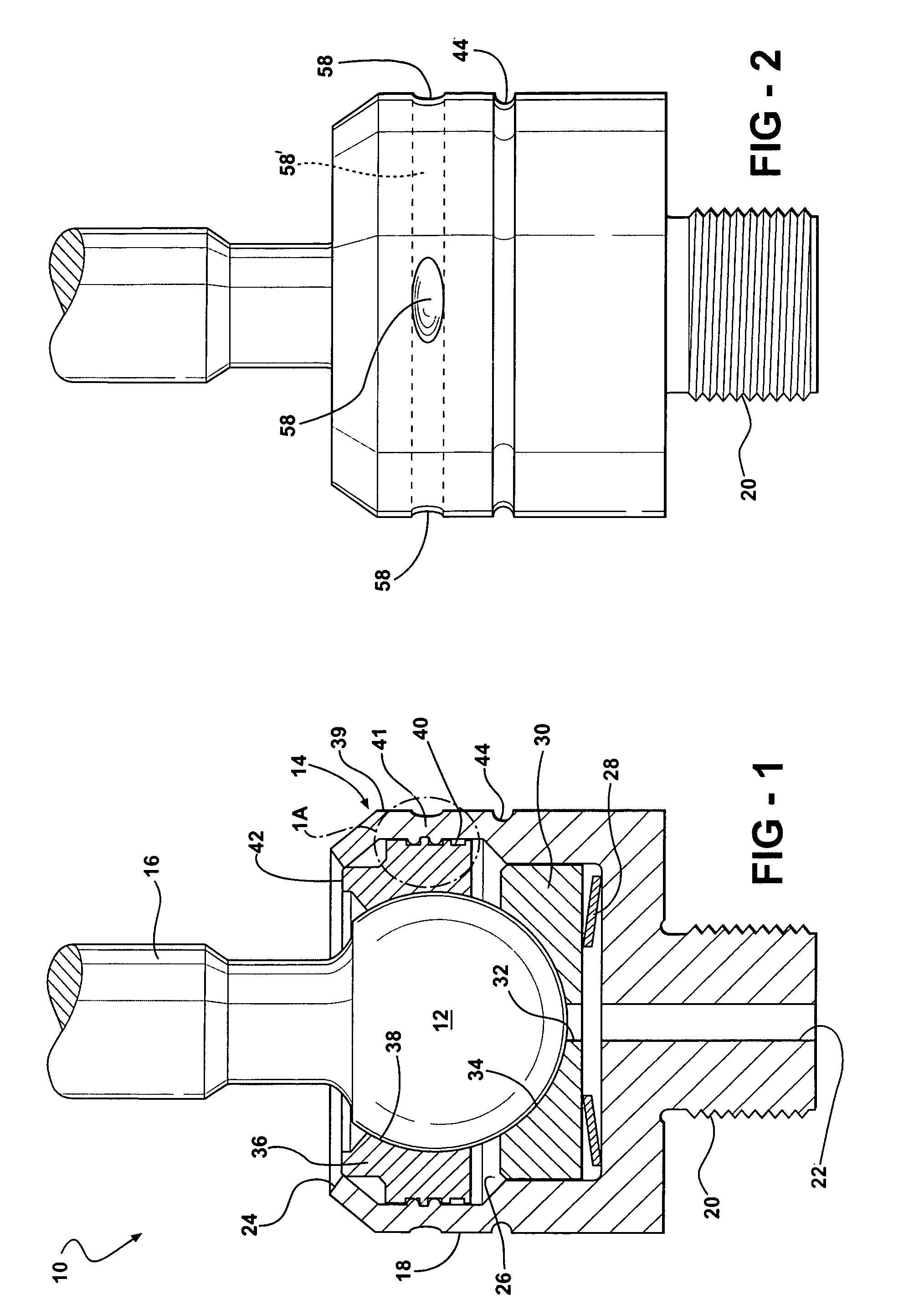
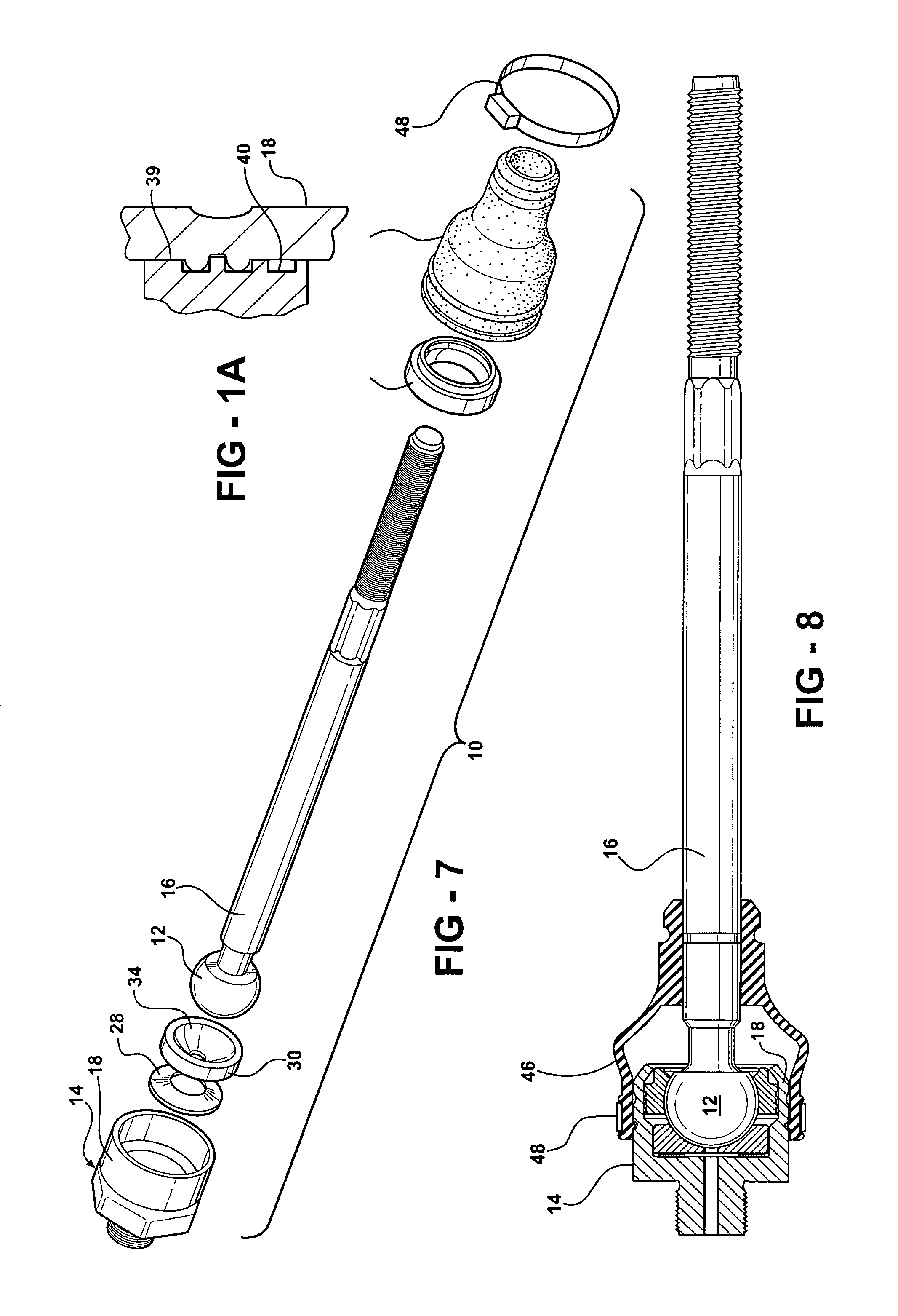
[0020]Referring to the Figures, wherein like numerals indicate like or corresponding parts throughout the several views, a ball-and-socket type mechanism is generally shown at 10. The ball and socket assembly 10 includes a ball portion 12 which is captured in a receiving socket of a ball joint housing, generally indicated at 14. Thus, the ball end 12 forms the male portion of a full articulating joint which facilitates the three-dimensional movement necessary to accommodate wheel turning and suspension travel in a vehicular chassis system. A shank 16 extends from the ball end 12 and acts as the anchoring device for connecting the ball joint assembly 10 within its intended application. For example, the shank 16 is shown in FIGS. 7 and 8 comprising an elongated shaft having a threaded end adapted to be connected, for example, to a vehicular suspension component.

[0021]The housing 14 is of the closed end type in which a generally cylindrical sidewall 18 is open at one end and closed at ...


PUM

PropertyMeasurementUnit
compression stressaaaaaaaaaa
compressiveaaaaaaaaaa
durabilityaaaaaaaaaa

Abstract

A method for assembling a ball and socket assembly (10) includes loading a housing (14) with a resilient preload washer (28), an inner bearing (30), a ball stud (12) and an outer bearing (36). A loading tool (50) forcefully compresses the assembled components, as a unit, to an overload compression condition (54), and then reduces the compression until an ideal compression condition (56) is achieved. The outer bearing (36) is staked in position while the loading tool (50) holds the assembled components in the ideal compression condition (56). Following the staking operation, the loading tool (50) can be removed, and a final crimping operation permanently sets the outer bearing (36) in position and holds the articulating components in the ideal, pre-load clearance established. The subject method is particularly well-suited for high production set-ups in which precise pre-load clearances must be achieved at high through put rates.

Description

BACKGROUND OF THE INVENTION[0001]1. Field of the Invention[0002]This invention relates to a ball and socket type joint of the type used in vehicular steering and chassis applications, and more particularly toward such a ball socket assembly in which a pre-established compressive load is captured between the articulating components during an assembly operation.[0003]2. Related Art[0004]Ball and socket type assemblies are typically used in vehicular applications where three-dimensional movement of a wheel, and in particular a steerable wheel, is required when a vehicle is turning and / or the suspension is accommodating movement over rough terrain. In the normal course of operation, ball sockets are subjected to very high stresses. These stresses are transmitted through the stud of the ball socket assembly into an associated suspension member, which may be a steering knuckle, control arm, steering link, rack and pinion unit or other feature.[0005]In particularly demanding applications, ...

Claims


Application Information

Patent Timeline
Patent Type & Authority Patents(United States)
IPC IPC(8): B21K1/10F16C11/00
CPCB23P11/005F16C11/0628F16C11/0647F16C11/0685F16C11/0695B23P2700/11Y10T29/4965F16C2229/00Y10T29/49853Y10T403/32737F16C2326/24F16C2326/05F16C11/08B23P11/00F16C27/00F16C33/00
Inventor SCHMIDT, GEORGEFITCH, LARRYDOHERTY, DONALD
Owner FEDERAL MOGUL WORLD WIDE LLC
Why Eureka
Try Eureka