
Signal detection method, signal detection system, signal detection processing program, and recording medium recorded with program thereof

a signal detection and signal detection technology, applied in the field of signal detection systems, signal detection processing programs, and recording media recorded with program thereof, can solve the problems of search based solely on lb>1/b> distance, inability to perform, etc., and achieve effective partial signal detection, narrow search space, and maintain search accuracy

Active Publication Date: 2010-01-26
NIPPON TELEGRAPH & TELEPHONE CORP
View PDF13 Cites 2 Cited by
  • Summary
  • Abstract
  • Description
  • Claims
  • Application Information

AI Technical Summary

Benefits of technology

The present invention provides a signal detection method that uses global and local pruning to efficiently search for a target signal within a large stored signal series. The method ensures a faster search time compared to previous methods while maintaining the same searching accuracy. The invention also uses the L1 distance measure to ensure the same search accuracy as the method described in Patent Document 1. Additionally, the invention includes a stored signal histogram grouping section that uses the L1 distance measure as the threshold for grouping, ensuring accuracy in all searches based on the L1 distance. The invention also includes a stored signal collation section that performs collation based on the similarity value obtained from the stored signal histogram grouping section, allowing for faster detection of the target signal.

Problems solved by technology

However, in the method of this Patent Document 2, because the method of using the L1 distance measure in global pruning was not clear, there was a shortfall in that a search based solely on the L1 distance, which is often highly accurate compared to the L2 distance, could not be performed.

Method used


Image

  • Signal detection method, signal detection system, signal detection processing program, and recording medium recorded with program thereof
  • Signal detection method, signal detection system, signal detection processing program, and recording medium recorded with program thereof
  • Signal detection method, signal detection system, signal detection processing program, and recording medium recorded with program thereof

Examples

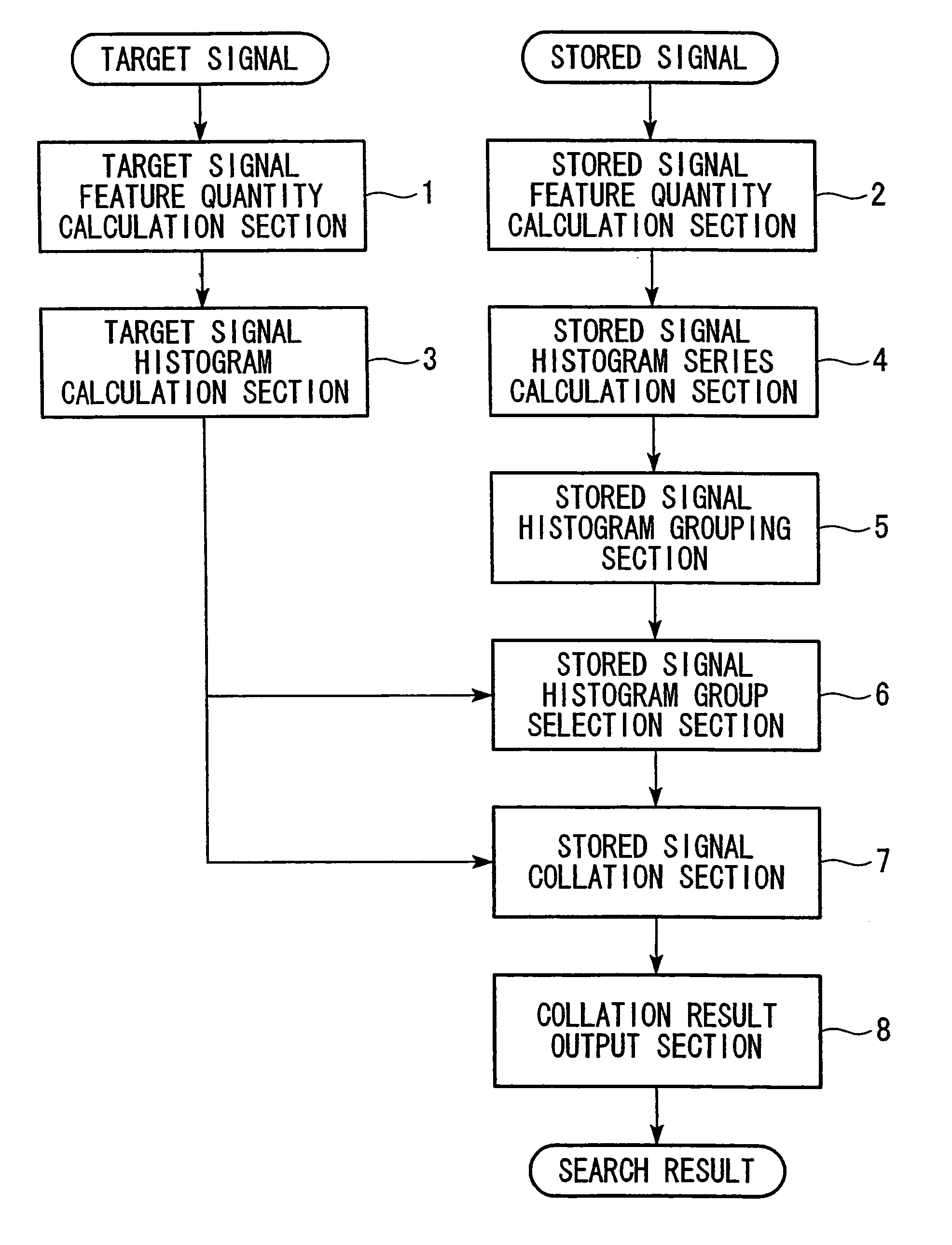

first embodiment

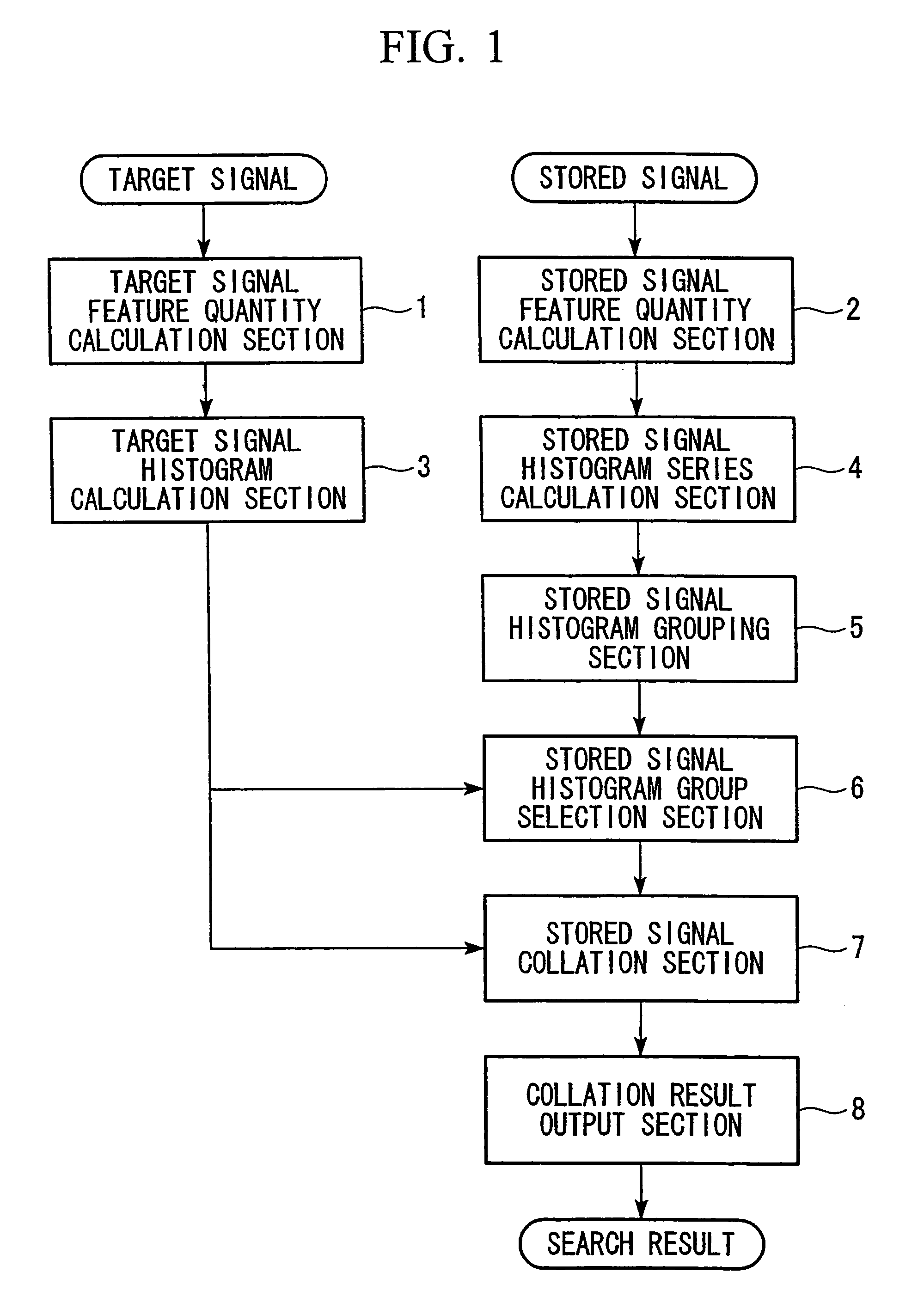
[0025]Next, an embodiment of the present invention is explained with reference to the drawings.

[0026]FIG. 1 is a block diagram showing a first embodiment of a signal detection system with the method of the present invention applied.

[0027]Although apparatuses subject to video signals are principally explained below, searching of sound signals can be performed by performing feature extraction from sound signals, which represent the target signals and the stored signals, in the target signal feature quantity calculation section 1 and the stored signal feature quantity calculation section 2 in the same configuration as mentioned below.

[0028]The signal detection system of the present first embodiment is configured by the target signal feature quantity calculation section 1, the stored signal feature quantity calculation section 2, a target signal histogram calculation section 3, a stored signal histogram series calculation section 4, a stored signal histogram grouping section 5, a stored...

second embodiment

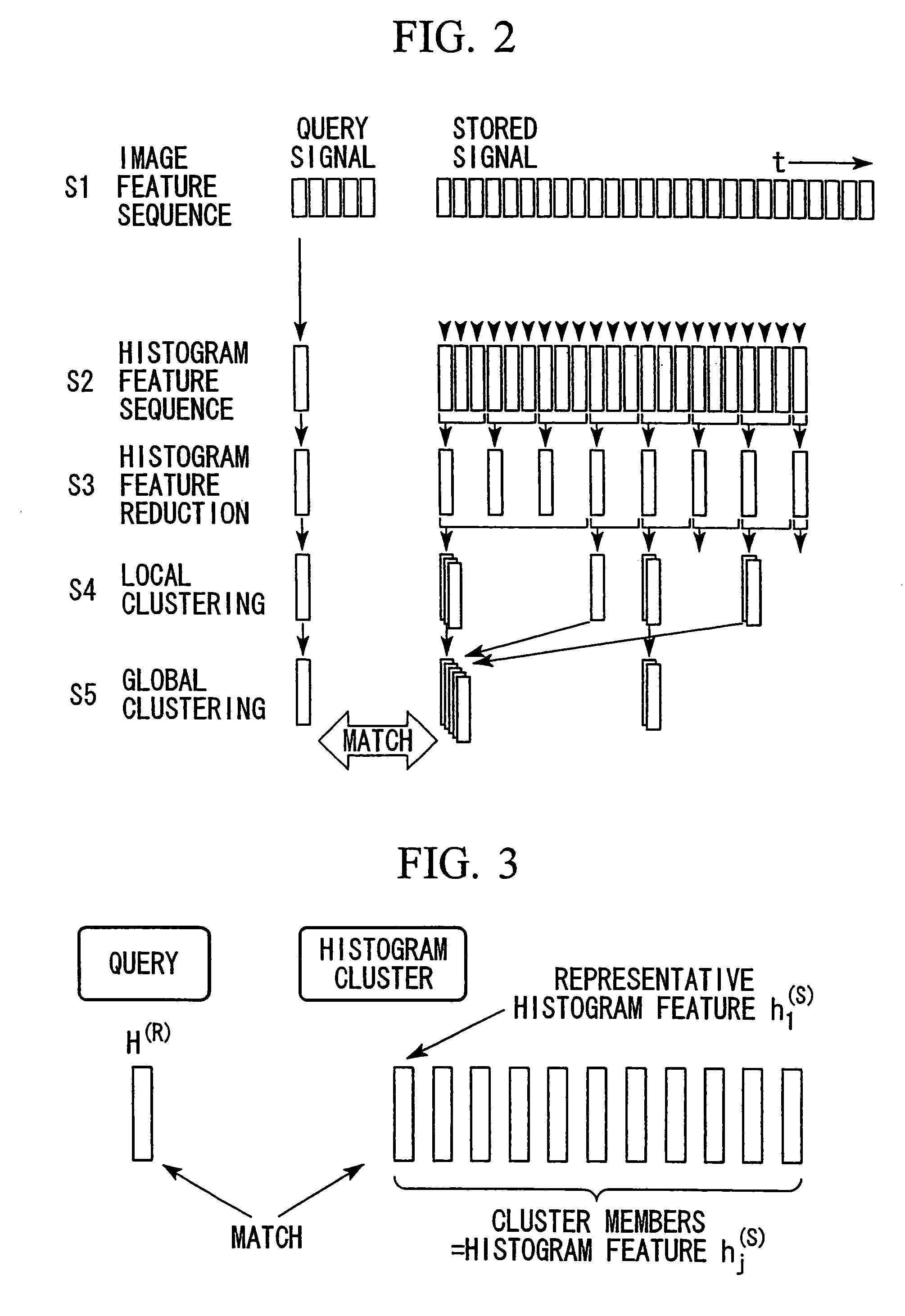
[0089]Next, a second embodiment is explained with reference to FIG. 1. The second embodiment is the same as the first embodiment in terms of the configuration. The point in which the second embodiment differs from the first embodiment is the point that following the stored signal histogram grouping section 5 performing local grouping represented by S4 in FIG. 2, these local groups are further grouped, and global grouping is performed.

[0090]Hereunder, the global grouping performed in the stored signal histogram grouping section 5 is explained.

[0091]In global grouping, groups are made such that the similarity level between all elements within the group with the representative histogram features of the group thereof become greater than the threshold θ(G). Here, the G of θ(G) represents that it is a threshold used with respect to global grouping. This threshold θ(G) is one based on the lower limit (the upper limit of the similarity level) of the L1 distance in regard to global grouping....

third embodiment

[0102]Next, a third embodiment is explained with reference to FIG. 4.

[0103]The third embodiment of the present invention shown in FIG. 4 is, in terms of the configuration, the same configuration as the first and the second embodiments shown in FIG. 1. The point of difference is that a stored signal histogram thinning section 9 is further provided between the stored signal histogram series calculation section 4 and the stored signal histogram grouping section 5.

[0104]That is to say, as explained in the first and the second embodiments, not all feature vectors in S2 of FIG. 2 are used, and the histogram series is created while moving the feature vectors by a fixed number as shown in S3 of FIG. 2, that is to say, by performing thinning.

[0105]For example, if the thinning number is made to be M=50, the number of histograms used at the time of histogram grouping can be compacted from 50 to 1.

[0106]In this manner, as well as being able to reduce the recording device capacity needed for rec...


PUM


Abstract

A signal detection system of the invention comprises: a target signal feature quantity calculation section which derives a feature quantity series from a target signal; a stored signal feature quantity calculation section which derives a feature quantity series from a stored signal; a target signal histogram calculation section which searches for a histogram of feature quantities in a target signal feature quantity series; a stored signal histogram series calculation section which obtains a histogram series in regard to a stored signal feature quantity series, by calculating a histogram of feature quantities; a stored signal histogram grouping section which groups histogram series, for which a similarity level satisfies a criteria; a stored signal histogram group selection section which selects groups which include an area to be output from a histogram group; a stored signal collation section which performs collation with respect to histograms of a histogram group, and obtains a similarity value; and a collation result output section which outputs the area collated by the similarity value, as a detection result.

Description

TECHNICAL FIELD[0001]The present invention relates to a signal detection method which detects by searching for a predetermined signal from within a stored signal series, or a signal similar to a part thereof, and is, for example, applicable to sound signal detection.[0002]Priority is claimed on Japanese Patent Application No. 2004-209088 filed Jul. 15, 2004, the content of which is incorporated herein by reference.BACKGROUND ART[0003]Conventionally, in regard to signal detection methods, signal searching methods, which have an object of detecting areas within a stored signal which is similar to the target signal, are known (for example, refer to “High-speed Signal Searching Method, Apparatus, and Recording Medium Thereof” of Patent Document 1).[0004]However, in the method of this Patent Document 1, since only local pruning (pruning refers to the exclusion of candidates as areas which should be collated without performing collation) was used, in a case where a large stored signal was...

Claims


Application Information

Patent Timeline
Patent Type & Authority Patents(United States)
IPC IPC(8): G06K9/00G06V10/56G10L15/00
CPCG06F17/30802G06F17/30825G06K9/4647G06K9/4652G06K9/6212G10L15/14G10L25/78G10L25/06G06F16/7328G06F16/785G06V10/507G06V10/56G06V10/758
Inventor KASHINO, KUNIOKIMURA, AKISATOKUROZUMI, TAKAYUKI
Owner NIPPON TELEGRAPH & TELEPHONE CORP
Learn More