Planar Light-emitting Device and Display Apparatus Having the Same

a technology of light-emitting devices and display devices, which is applied in the direction of mechanical devices, lighting and heating devices, instruments, etc., can solve the problems that the backlight unit cannot be reduced in thickness as desired, and achieve the effect of reducing thickness, suppressing light loss, and reducing light emission efficiency

Inactive Publication Date: 2008-06-26
CITIZEN ELECTRONICS CO LTD
View PDF6 Cites 0 Cited by
  • Summary
  • Abstract
  • Description
  • Claims
  • Application Information

AI Technical Summary

Benefits of technology

[0007]The present invention has been made in view of the above-described circumstances. Accordingly, an object of the present invention is to provide a planar light-emitting device capable of further suppressing the loss of light from a l...

Problems solved by technology

Thus, the backlight unit canno...

Method used


Image

  • Planar Light-emitting Device and Display Apparatus Having the Same
  • Planar Light-emitting Device and Display Apparatus Having the Same
  • Planar Light-emitting Device and Display Apparatus Having the Same

Examples


Embodiment Construction

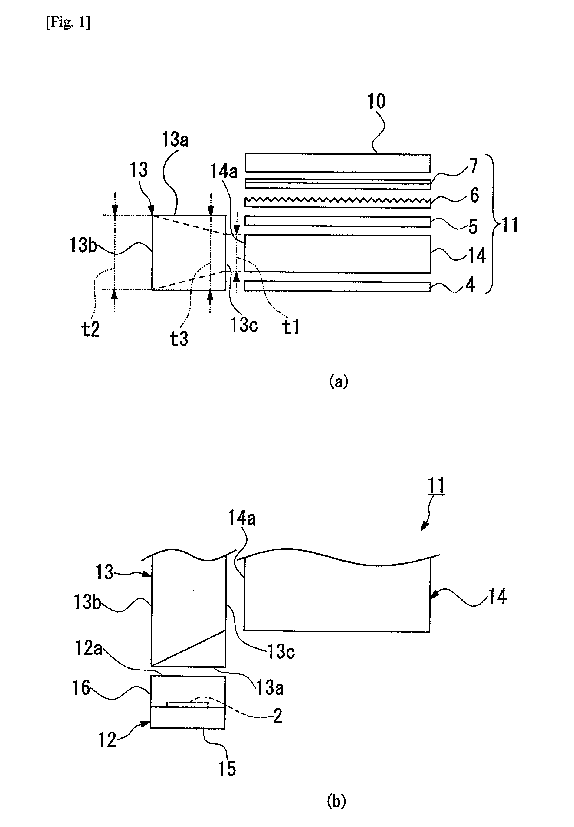
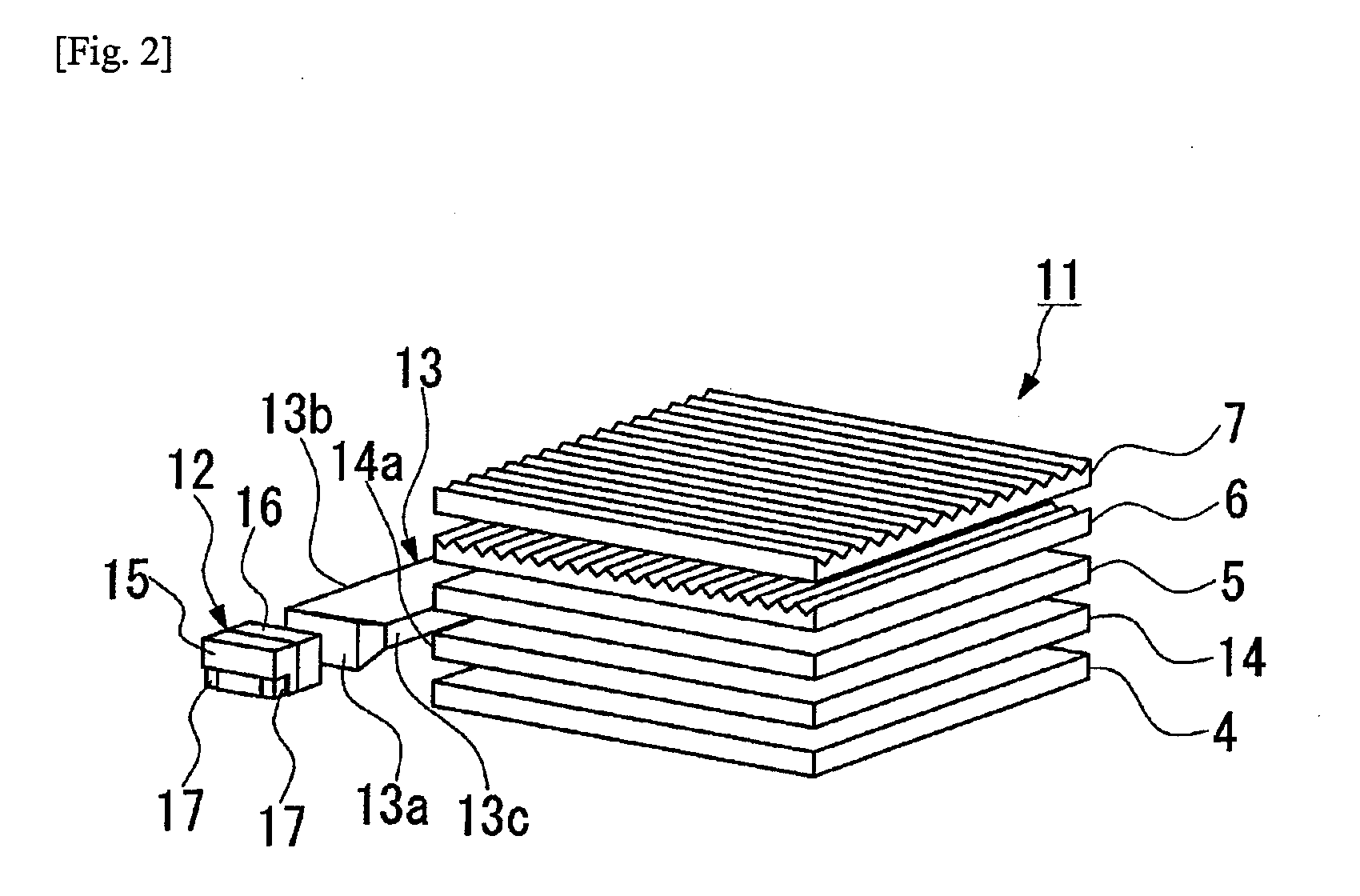
[0029]One embodiment of a planar light-emitting device and display apparatus having the same according to the present invention will be described below with reference to FIGS. 1a to 2.

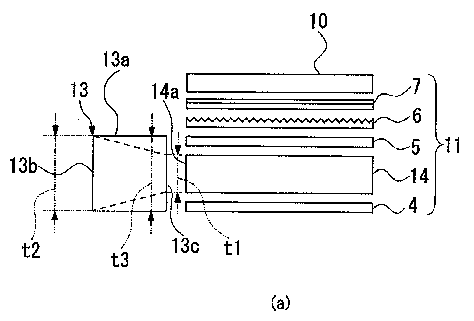
[0030]The display apparatus in this embodiment is, as shown in FIGS. 1a, 1b and 2, a liquid crystal display apparatus applicable, for example, to liquid crystal displays of mobile phones and PDAs. The display apparatus has a liquid crystal display panel (image display panel) 10 and a backlight unit (planar light-emitting device) 11 disposed at the back of the liquid crystal display panel 10.

[0031]The backlight unit 11 in this embodiment has a light-emitting package (light source) 12, an elongate first lightguide plate 13, a flat plate-shaped second lightguide plate 14, a diffuser sheet 5, a combination of a first prism sheet 6 and a second prism sheet 7, and a reflective sheet 4. The light-emitting package 12 emits light from light-emitting elements 2 through an exit surface 12a thereof. The first ligh...


PUM


Abstract

A planar light-emitting device includes an elongate first lightguide plate (13) having a light entrance end surface (13a) disposed facing an exit surface (12a) of a light-emitting package (12), a reflecting side surface (13b) extending substantially at right angles to the light entrance end surface to reflect light entering through the light entrance end surface, and a light exit side surface (13c) facing the reflecting side surface, and a flat plate-shaped second lightguide plate (14) having a light entrance side edge surface (14a) facing the light exit side surface (13c). The first lightguide plate is configured to satisfy the condition of t1<t2≦t3, where: t1, t2 and t3 are the respective heights of the light exit side surface (13c), the reflecting side surface (13b) and the light entrance end surface (13a). The surfaces of the first lightguide plate other than the light entrance end surface (13a) and the light exit side surface (13c) are reflecting surfaces.

Description

[0001]This application claims priority under 35 U.S.C. §119 to Japanese Patent Application No. JP2006-349940 filed on Dec. 26, 2006, the entire contents of which are hereby incorporated by reference.BACKGROUND[0002]The present invention relates to a planar light-emitting device for use in liquid crystal displays of mobile phones and the like, for example, and also relates to a display apparatus having the planar light-emitting device.RELATED CONVENTIONAL ART[0003]Liquid crystal display apparatus for displaying letters or images have been widely used in displays of mobile phones, personal digital assistants (PDAs), etc. These liquid crystal display apparatus employ a backlight unit that applies illuminating light to a liquid crystal display panel from the back thereof to enhance the luminance of the display screen. A typical backlight unit is arranged as follows. As shown in FIG. 3, a light-emitting package 3 having a light-emitting element 2, for example, an LED light source, is ins...

Claims


Application Information

Patent Timeline
IPC IPC(8): F21V8/00
CPCG02B6/0028
Inventor MIYASHITA, JUNJIMIYASHITA, TAKUMI
Owner CITIZEN ELECTRONICS CO LTD
Why Eureka
Try Eureka