

Optical element and objective optical system
- Summary
- Abstract
- Description
- Claims
- Application Information
AI Technical Summary
Benefits of technology
Problems solved by technology
Method used
Image

Examples
example
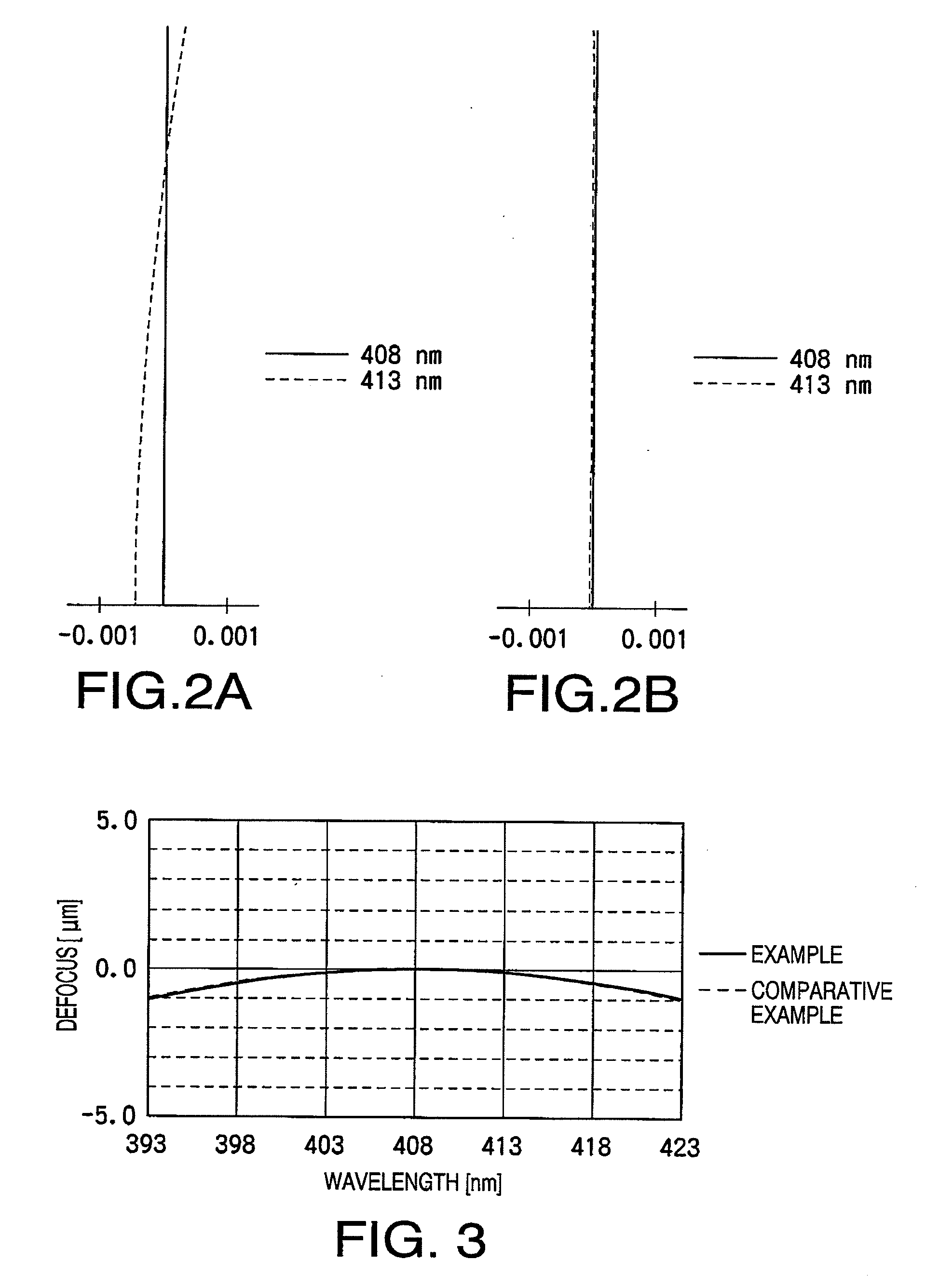
[0068]The following Table 1 shows concrete specifications of the objective optical system 100 according to an example. Table 2 shows a specific numerical configuration of the optical information recording / reproducing device provided with the objective optical system 100 shown in Table 1.
TABLE 1Wavelength λ (nm)408Focal Length f (mm)1.000NA2.000Magnification0.000SAM5 (mm)0.0003CA5 (mm)−0.0005
TABLE 2SurfaceNo.rdn (408 nm)n (413 nm)0—∞1.000001.00000Light Source14.4422.0001.524241.52351Objective2165.1692.6371.000001.00000Lens30.5000.7102.378322.37028SIL4∞—
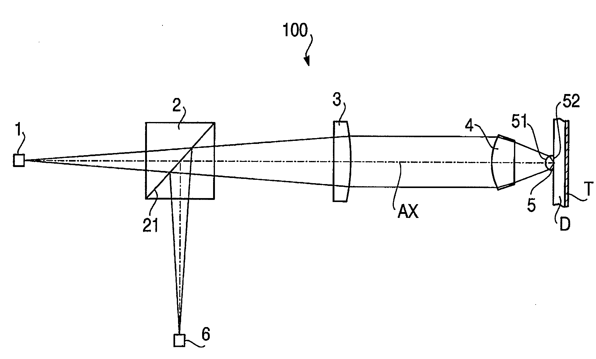
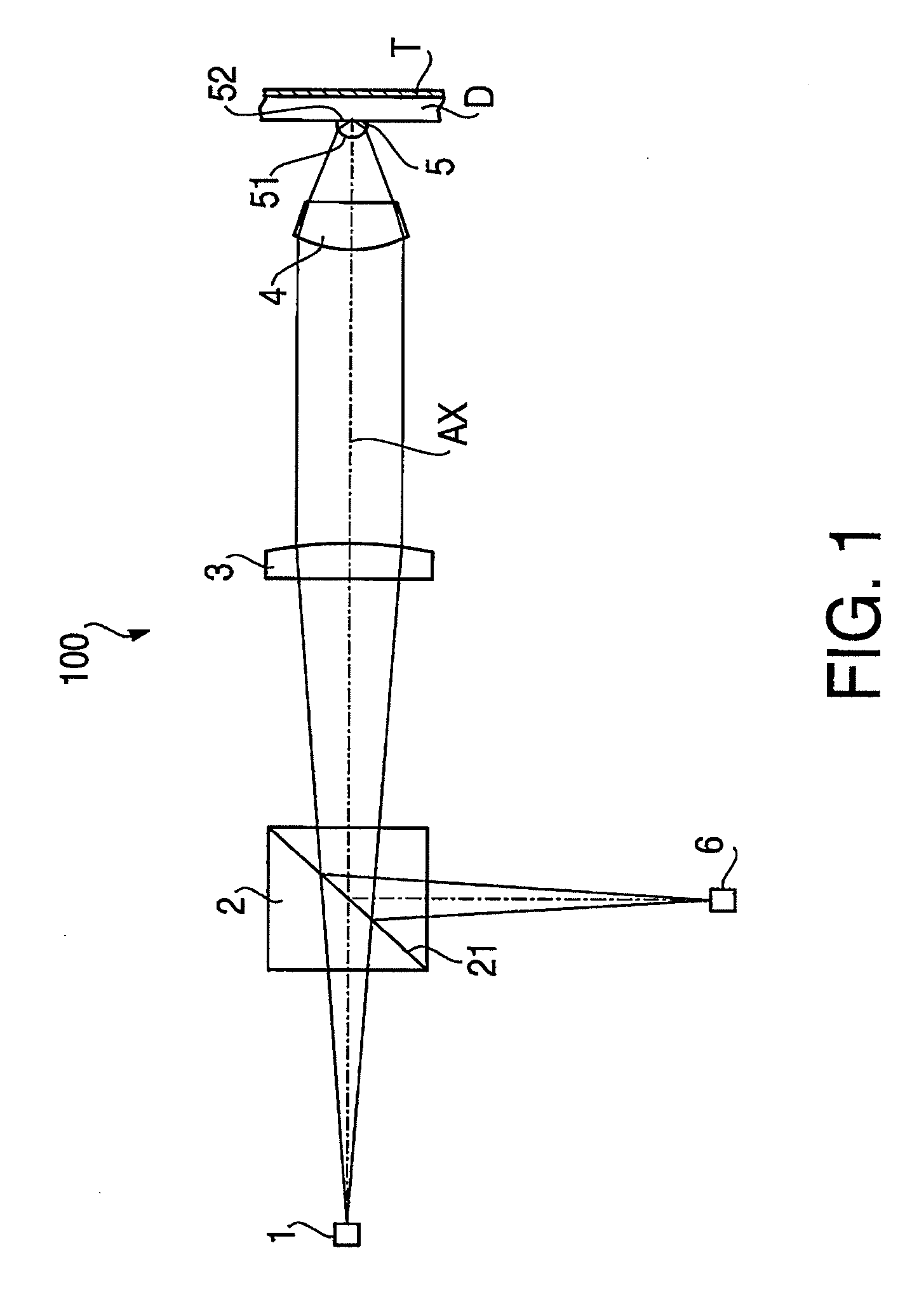
[0069]As indicated by the “Magnification” in Table 1, the laser beam is incident upon the objective lens 4 as a collimated beam when the information recording or information reproducing is performed for the optical disc D.
[0070]In the Table 2, the surface #0 represents a light source, the surfaces #1 and #2 represent the front surface (light source side surface) and rear surface (optical disc side surface) of the objective lens 4, and ...
PUM
 Abstract
Description
Claims
Application Information