Objective lens for optical pickup device and optical pickup device

A technology for an optical pickup device and an objective lens, which can be applied to optics, optical components, components of TV systems, etc., and can solve problems such as unfavorable miniaturization and increase in cost.

Inactive Publication Date: 2015-09-16
KONICA MINOLTA INC
View PDF8 Cites 0 Cited by
  • Summary
  • Abstract
  • Description
  • Claims
  • Application Information

AI Technical Summary

Problems solved by technology

[0005] As a method for appropriately recording / reproducing information on any of BD, DVD, and CD, while maintaining compatibility, it is considered to selectively switch BD according to the recording density of the optical disc on which information is recorded / reproduced. The method of using optical systems and optical systems for DVD and CD, but requires multiple optical systems, so it is not conducive to miniaturization and increases the cost

Method used


Image

  • Objective lens for optical pickup device and optical pickup device
  • Objective lens for optical pickup device and optical pickup device
  • Objective lens for optical pickup device and optical pickup device

Examples


Embodiment 1

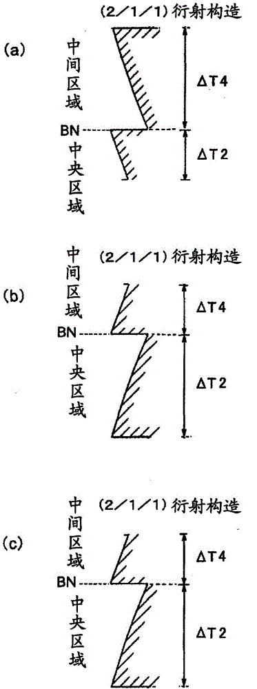
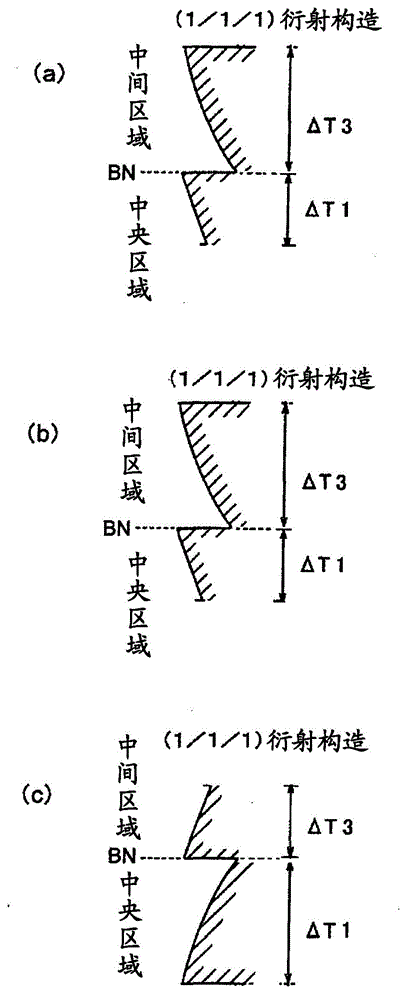
[0317] Table 1 shows the lens data of Example 1. This embodiment is an example in which the steps of the first foundation structure and the third foundation structure face the direction opposite to the optical axis, and the steps of the second foundation structure and the fourth foundation structure face the direction of the optical axis. The focal length of the BD is 2.2mm, and here the position is determined as a relatively short value. Figure 16 Shows the spacing of the individual infrastructures. exist Figure 16 In the graph, the vertical axis represents the pitch P (mm), the horizontal axis represents the height from the optical axis, and the left side represents the central area and the right side represents the middle area with the boundary BN as the boundary. P1, P2, P3, and P4 are the values ​​of the distances between the first foundation structure, the second foundation structure, the third foundation structure, and the fourth foundation structure closest to the bo...

Embodiment 2

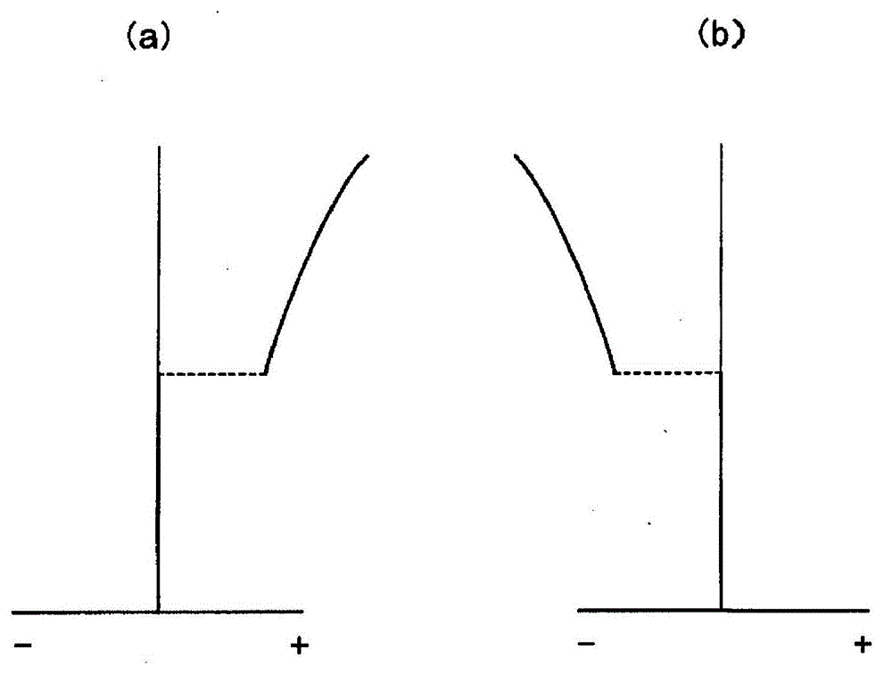
[0333] Table 2 shows the lens data of Example 2. This embodiment is an example in which the steps of the first foundation structure and the third foundation structure face the direction opposite to the optical axis, and the steps of the second foundation structure and the fourth foundation structure face the direction of the optical axis. The focal length of BD is a relatively short value like 1.77mm. Figure 17 Shows the spacing of the individual infrastructures. according to Figure 17 It can be known that P1 and P3 are positive values, the absolute value of P3 is greater than P1, P2 and P4 are negative values, and the absolute value of P2 is greater than P4. Therefore, as shown in Table 6 described later, it can be seen that P4-P2>0 and P3-P1>0. in addition, Figure 11A diagram of longitudinal spherical aberration when the CD in Example 2 is used is shown. Such as Figure 11 As shown, spherical aberration occurs on the short side of the information recording surface o...

Embodiment 3

[0349] Table 3 shows the lens data of Example 3. This embodiment is an example in which the steps of the first foundation structure and the third foundation structure face the direction opposite to the optical axis, and the steps of the second foundation structure and the fourth foundation structure face the direction of the optical axis. The focal length of BD is a relatively short value like 1.77mm. As shown in Table 6 described later, it can be seen that P4-P2>0 and P3-P1>0. in addition, Figure 12 The longitudinal spherical aberration diagram in Example 3 when CD is used is shown. Such as Figure 12 As shown, spherical aberration occurs on the short side of the information recording surface of the CD on the outer side compared with the middle area, and it can be seen from this that appropriate flare expression can be performed.

[0350] [table 3]

[0351] ◆Specification

[0352]

[0353] ◆Configuration

[0354]

[0355] *di represents the displacement from the...


PUM

PropertyMeasurementUnit
thicknessaaaaaaaaaa
thicknessaaaaaaaaaa
refractive indexaaaaaaaaaa

Abstract

Provided is an objective lens with which three types of optical disks, BB / DVD / DC, are interchangeable using a typical objective lens, and with which high-order aberrations can be suppressed and formability can be increased; also provided is an optical pickup device using said objective lens. The objective lens has a central region wherein second basic structures having a blazed structure are superposed, and an intermediate region wherein fourth basic structures having a blazed structure are superposed. On either side of the boundary between the central region and the intermediate region, the pitch P2 at the position of the second basic structures of the central region nearest to the boundary, and the pitch P4 at the position of the fourth basic structures of the intermediate region nearest to the boundary, fulfill the relationship P4 - P2 > 0 when the codes corresponding to the orientation of the steps is considered. Thus, the power in the intermediate region is greater than the power in the central region, and consequently a negative spherical aberration of the base aspherical surface remains in the intermediate region, and it is possible to emit flares when a CD is used.

Description

technical field [0001] The present invention relates to an optical pickup device and an objective lens capable of recording and / or reproducing information (recording / reproducing) interchangeably with respect to different types of optical discs. Background technique [0002] In recent years, in the optical pickup device, the laser light source used as a light source for reproducing information recorded on the optical disc and recording information on the optical disc has been shortened. For example, laser light sources with a wavelength of 390 to 415 nm such as blue-violet semiconductor lasers got practical. If these blue-violet laser light sources are used, in the case of using an objective lens with the same numerical aperture (NA) as DVD (Digital Versatile Disc), it is possible to record 15 to 20 GB of information on an optical disc with a diameter of 12 cm. When the NA of the element is increased to 0.85, information of 23 to 25 GB can be recorded on an optical disc with...

Claims


Application Information

Patent Timeline
Patent Type & Authority Patents(China)
IPC IPC(8): G11B7/1353G02B13/00G02B13/18
CPCG11B2007/0006G11B7/1367G11B7/1374H04N5/2254G11B7/1353G02B27/4238G11B7/13922
Inventor 立山清乃
Owner KONICA MINOLTA INC
Why Eureka
Try Eureka