Hydraulic chuck with independently moveable jaws

a hydraulic chuck and jaw technology, applied in the direction of chucks, mechanical devices, manufacturing tools, etc., can solve problems such as jaws retraction

Inactive Publication Date: 2010-02-02
NOVATEK IP
View PDF41 Cites 32 Cited by
  • Summary
  • Abstract
  • Description
  • Claims
  • Application Information

AI Technical Summary

Problems solved by technology

Increasing hydraulic pressure in the first chamber may cause a jaw to protract in the direction of the workpiece, and increasing hydraulic pressure to the second chamber may cause the jaw to retract.

Method used


Image

  • Hydraulic chuck with independently moveable jaws
  • Hydraulic chuck with independently moveable jaws
  • Hydraulic chuck with independently moveable jaws

Examples


Embodiment Construction

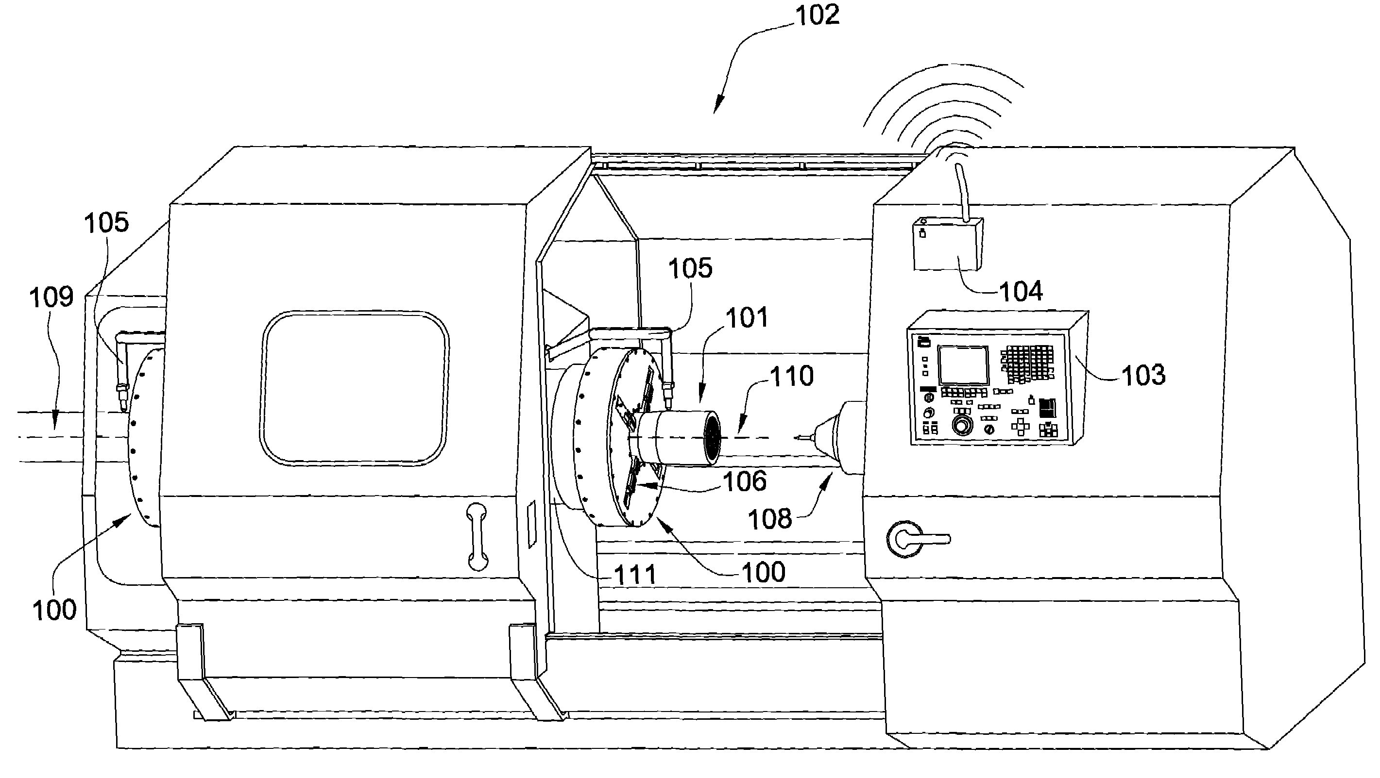
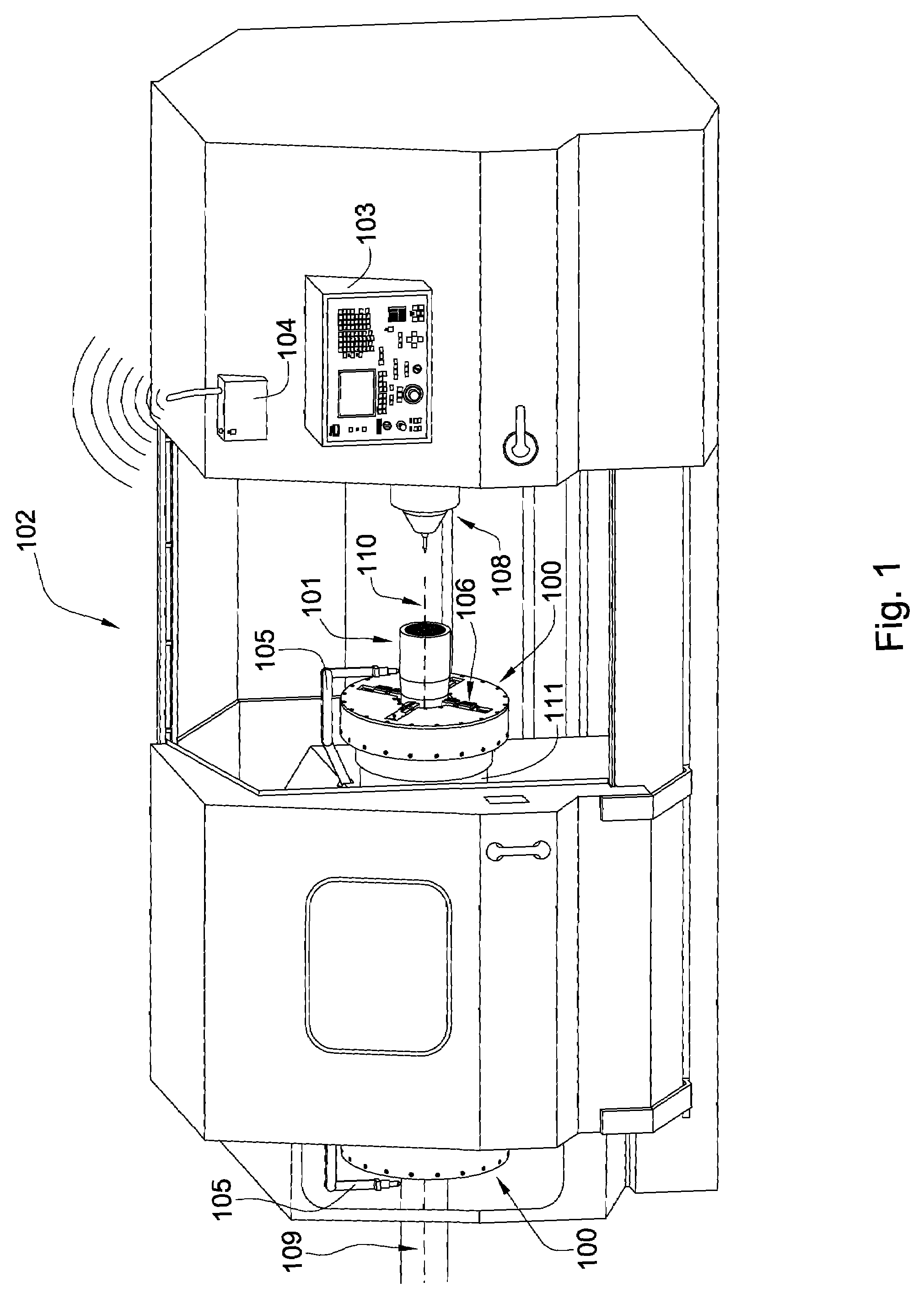
[0024]Referring now to FIG. 1, when a workpiece 101 such as a drill pipe having an axis 109 is machined with a lathe assembly 102, it becomes necessary to couple the workpiece 101 to a rotating portion of the lathe assembly 102 known as a spindle 111. A chuck 100 may provide an interface between the spindle 111 of the lathe assembly 102 and the workpiece 101. In some situations, such as the one shown in this figure, greater stability may be achieved through the use of two chucks 100 or more. As the lathe assembly 102 is designed to rotate the workpiece 101 about a central axis 110 at what may at times be significant speeds, machining requirements often make it very desirable that rotational axes of the workpiece 101, chuck 100, and lathe 102 are aligned to a high degree of precision.

[0025]It is generally the case that the chuck 100 and lathe 102 do not require realignment whenever a new workpiece 101 is dialed in to the lathe 102, so for most practical purposes if the rotational axi...


PUM

PropertyMeasurementUnit
hydraulic fluid pressureaaaaaaaaaa
hydraulic pressureaaaaaaaaaa
dimensionsaaaaaaaaaa

Abstract

A method of dialing a workpiece having an axis into a chuck includes providing a chuck assembly having a plurality of independent hydraulically controlled jaws distributed about a central axis, each jaw having first and second hydraulic chambers. The method further includes the steps of inserting a portion of the workpiece into the chuck assembly, pumping hydraulic fluid uniformly into each of the first chambers until the jaws are substantially touching the perimeter of the workpiece, and adjusting one or more of the jaws to align the axis of the workpiece with the central axis of the chuck assembly by pumping hydraulic fluid into at least one of the chambers of at least one of the jaws. The method also includes the step of pumping hydraulic fluid uniformly into each of the first chambers until the jaws are clamped around the perimeter of the workpiece at a predetermined pressure.

Description

BACKGROUND OF THE INVENTION[0001]Many of the common items that make modern life convenient are created by machining raw material such as metal or wood as it rotates on a lathe spindle. Often lathes are also used to modify previously manufactured objects such as pipes and rods. Many of these machined items require precise dimensions and tolerances to function properly, making it crucial that they are adequately aligned to an axis of rotation of the lathe. Lathes also typically require an attachment mechanism to anchor the workpiece in place as it rotates with the spindle. To address these issues chucks are frequently used in conjunction with lathes and other rotating tools.[0002]In spite of their utility, however, chucks used typically in the art have some drawbacks. For example, dialing a workpiece into a chuck may require excessive time before the axes of the workpiece and the chuck are suitably aligned. Manually tightening and loosing of chuck jaws may also introduce inconsistenci...

Claims


Application Information

Patent Timeline
Patent Type & Authority Patents(United States)
IPC IPC(8): B23B31/30
CPCB23B31/101B23B31/302B23B2231/30Y10T82/27Y10T279/1283Y10T279/21Y10T82/10Y10T279/1291Y10T279/1208Y10T82/26
Inventor HALLREYNOLDS, JAYWACH, RYAN
Owner NOVATEK IP
Why Eureka
Try Eureka