Ophthalmic photography apparatus

a technology of ophthalmic photography and equipment, applied in the field of ophthalmic photography equipment, can solve problems such as the increase of equipment cos

Inactive Publication Date: 2010-02-02
KOWA CO LTD
View PDF2 Cites 44 Cited by
  • Summary
  • Abstract
  • Description
  • Claims
  • Application Information

AI Technical Summary

Benefits of technology

[0025]In the present invention, a plurality of light sources are provided for illuminating an anterior ocular segment, and the light sources are selectively turned on, making it possible to photograph or observe a striped pattern necessary for measuring the tear fluid or interference stripes formed by the tear film of the anterior ocular segment. The symptoms of dry eye can therefore be diagnosed in a diverse manner.

Problems solved by technology

When attempts have been made to observe the tear film interference stripes and to measure the amount of tear fluid by a multi-use machine, the lattice-shaped slit placed in the optical system during tear fluid measurement must be removed during the observation of the tear film interference stripes, resulting in a complex configuration and causing the equipment cost to go up.

Method used


Image

  • Ophthalmic photography apparatus
  • Ophthalmic photography apparatus
  • Ophthalmic photography apparatus

Examples


embodiment 1

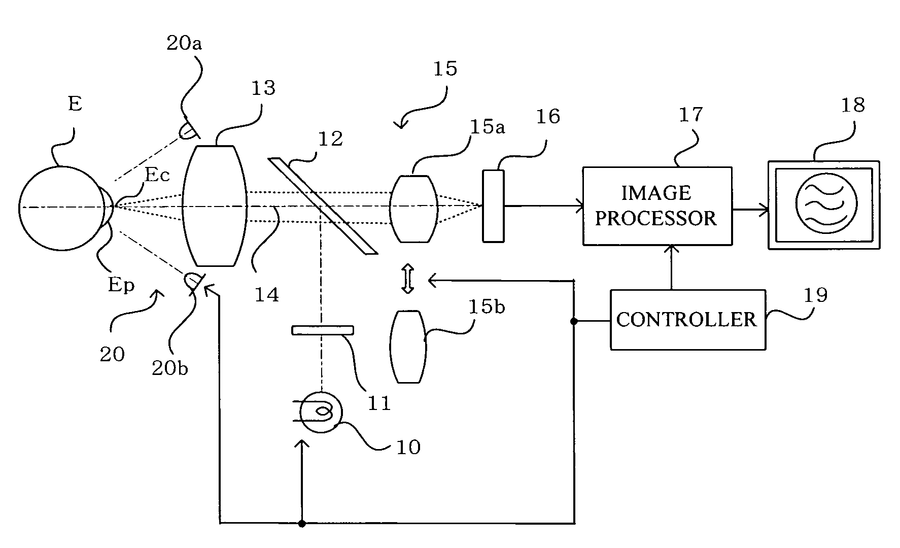
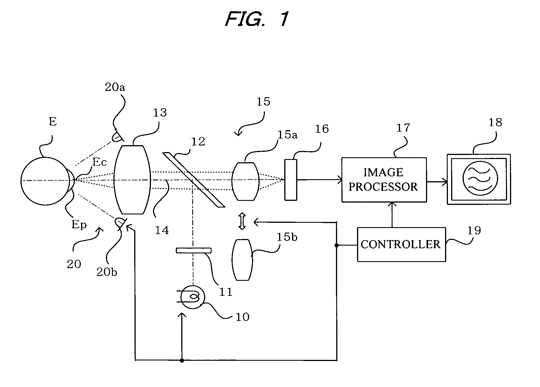
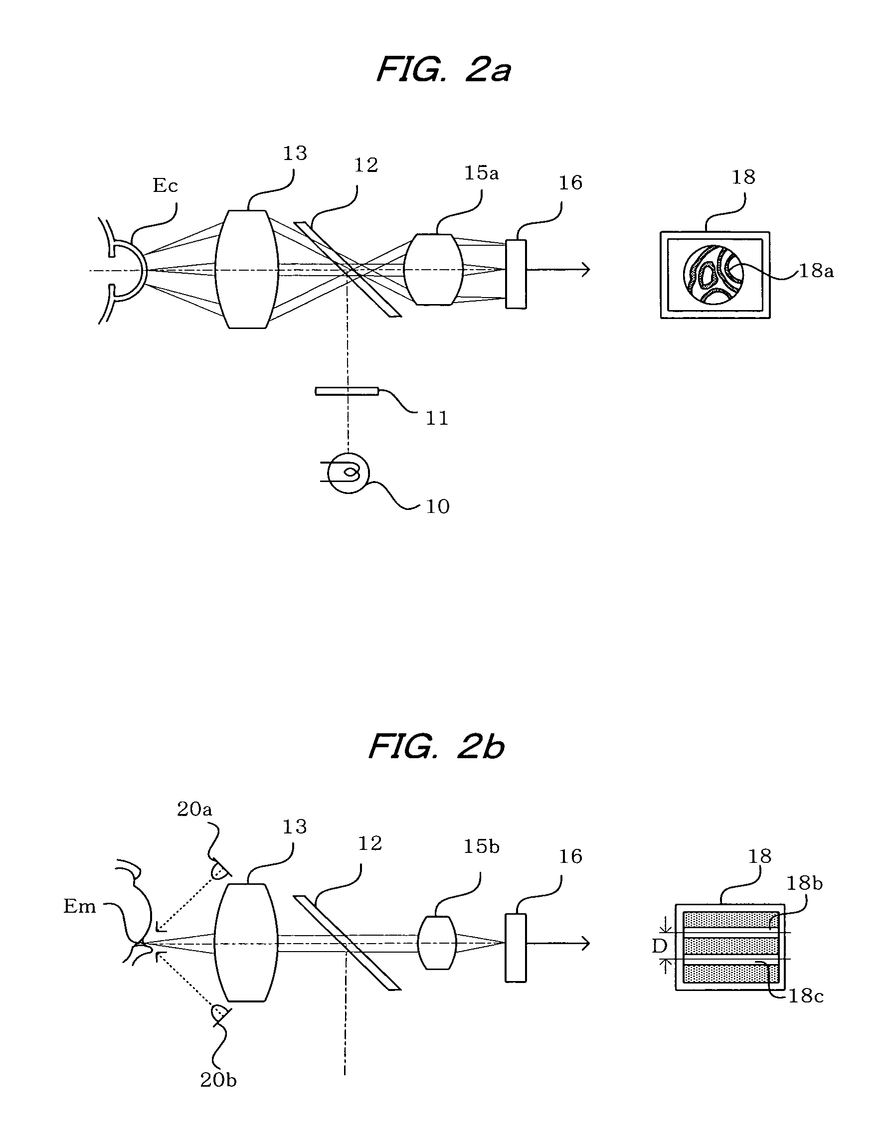
[0039]FIG. 1 shows a configuration of the ophthalmic photography apparatus according to an embodiment of the present invention. In the drawing, numerical symbol 10 indicates a halogen lamp or other low-magnification light source for use as a first light source. Light from the low-magnification light source 10 passes through a polarization plate 11, is reflected by a half mirror 12 that has a reflection coefficient of about 30% and functions as an optical path splitting means, is made coaxial with an optical axis 14 of a photographing optical system, and is made to irradiate the anterior ocular segment Ep of a subject's eye E via an objective lens 13.

[0040]Light reflected from the cornea Ec of the subject's eye E forms an image on a CCD 16 as a photography means, via the objective lens 13, the half mirror 12, and a variable power lens 15. At this time, the optical axis 14 of the photographing optical system is adjusted so as to be at the center of the cornea Ec of the subject's eye.

[...


PUM


Abstract

To observe interference stripes produced by tear fluid, a low magnification light source 10 is turned on to illuminate the outermost layer of a tear film on the cornea Ec of a subject's eye. Light reflected from the cornea Ec forms an image on a CCD 16, and an interference stripes pattern 18a created by the lipid film on the cornea is displayed on a monitor 18. To measure the amount of tear fluid, light-emitting elements 20a, 20b of a high-magnification light source are turned on to irradiate a tear fluid meniscus Em that has accumulated on the lower eyelid portion of the anterior ocular segment. Light reflected on the surface of the meniscus Em forms an image on the CCD 16, and images 18b, 18c of the light-emitting elements 20a, 20b are displayed on the monitor 18 as clear images separated by an interval D. The amount of tear fluid can be quantitatively measured by measuring the interval D. A single such structure allows interference stripes created by the tear film of the anterior ocular segment to be observed and the amount of tear fluid to be measured.

Description

CROSS-REFERENCE TO RELATED APPLICATIONS[0001]This application is a U.S. national stage application of International Application No. PCT / JP2006 / 311387, filed Jun. 7, 2006, claiming a priority date of Jul. 1, 2005, and published in a non-English language.TECHNICAL FIELD[0002]The present invention relates to an ophthalmic photography apparatus, and more specifically to an ophthalmic photography apparatus for photographing the anterior ocular segment of a subject's eye for the purpose of diagnosing dry eye and the like.BACKGROUND ART[0003]When a subject's eye is affected by dry eye, there is a risk that it will complicate corneal epithelial disorders, conjunctival disorders, and various other ophthalmic diseases. Therefore, the anterior ocular segment of a subject's eye is observed or photographed to diagnose the dry eye and other symptoms. For example, the degree of advancement of dry eye is qualitatively diagnosed through observation of interference stripes formed by the tear fluid in...

Claims


Application Information

Patent Timeline
Patent Type & Authority Patents(United States)
IPC IPC(8): A61B3/14
CPCA61B3/101
Inventor SUZUKI, TAKAYOSHI
Owner KOWA CO LTD
Why Eureka
Try Eureka