Socket assembly

a socket and assembly technology, applied in the direction of coupling device details, coupling device connections, contact members penetrating/cutting insulation/cable strands, etc., can solve the problems of clutter and disturbance around the socket area, still no connection line, and inconvenience for users

Inactive Publication Date: 2010-02-02
LIAO SHENG HSIN
View PDF5 Cites 46 Cited by
  • Summary
  • Abstract
  • Description
  • Claims
  • Application Information

AI Technical Summary

Benefits of technology

[0011]The present invention has advantageous effects as follows. The socket assembly of the present invention is combined with a connecting line and an electrical connector, and the connecting line and the electrical connector are movably provided in the socket body, so that the connecting line and the electrical connector can be drawn out of the socket body freely or stored in the socket body. When a user wants to use the connecting line and the electrical connector, he / she only needs to draw the connecting line and the electrical connector out of the socket body. In this way, the socket assembly can provide a connecting line and an electrical connector quickly, so that the user does not need to spend time in finding a connecting line and an electrical connector. Therefore, it is very convenient to use the present invention. Further, when the connecting line and the electrical connector are not in use, it is not necessary to remove them from the socket assembly. The connecting line and the electrical connector can be stored in the socket body without getting lost. Therefore, it is convenient in the subsequent use, and will not cause clutter and disturbance. Thus, it is very convenient for the user to use the socket assembly of the present invention.
[0012]In order to further understand the characteristics and technical contents of the present invention, a detailed description is made with reference to the accompanying drawings. However, it should be understood that the drawings are illustrative only and not to be used to limit the present invention thereto.

Problems solved by technology

Although the conventional socket can be provided with an electrical connector suitable for plugging into an electronic product, it still does not have a connecting line.
Further, the connecting line may get lost easily after removal, causing inconvenience for the user.
If the connecting line is not removed, it may result in clutter and disturbance around the socket area.

Method used


Image

  • Socket assembly
  • Socket assembly
  • Socket assembly

Examples


first embodiment

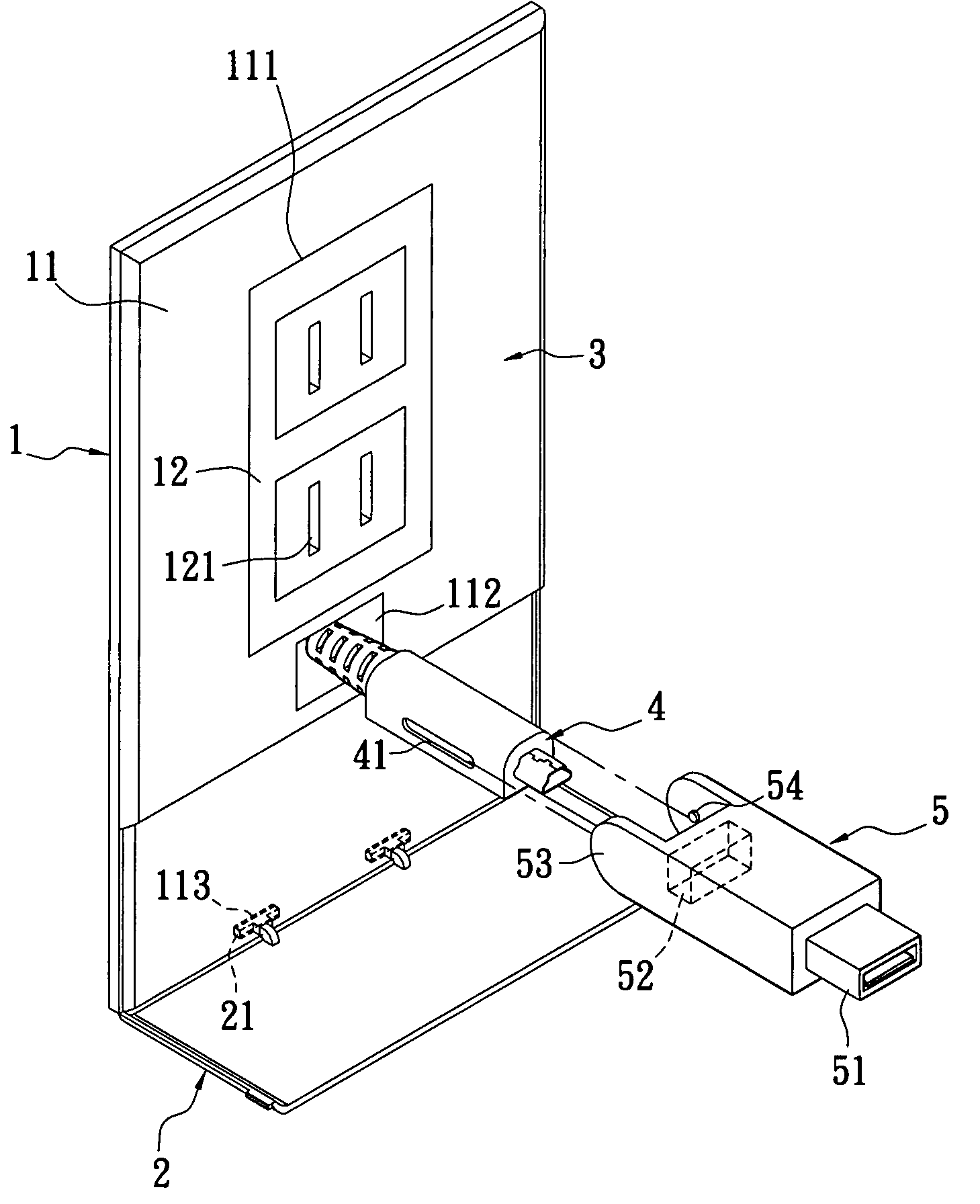
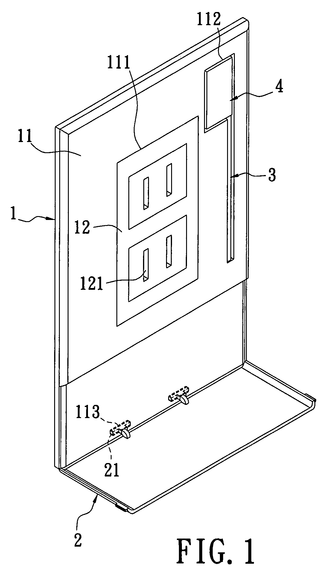
[0023]The present invention provides a socket assembly. Please refer to FIGS. 1 to 3, which show the socket assembly of the present invention. The socket assembly includes a socket body 1, a supporting plate 2, a connecting line 3 and an electrical connector 4. The socket body 1 comprises a panel 11 and at least one socket unit 12. The panel 11 is formed by means of laminating a front plate and a rear plate. The panel 11 has an engaging portion 111. In the present embodiment, the engaging portion 111 is a through hole for engaging an outer edge of the socket unit 12 correspondingly.

[0024]The panel 11 is provided with an elongated receiving trough 112. The receiving trough 112 is recessed in the panel 11. The shape of the receiving trough 112 substantially corresponds to profiles of the connecting line 3 and the electrical connector, thereby receiving the connecting line 3 and the electrical connector 4. In the present embodiment, the receiving trough 112 is located at one side of th...

second embodiment

[0031]Further, please refer to FIG. 4. In the present invention, the receiving trough 112 is adjacent to one side of the socket unit 12. The connecting line 3 is wrapped spirally, thereby having elasticity for extension. Therefore, the electrical connector 4 can be moved to a desired position more flexibly.

third embodiment

[0032]Further, please refer to FIG. 5. In the present, the receiving trough 112 is located on the bottom of the socket unit 12. The receiving trough 112 is provided in the panel 11 to penetrate the inside of the panel 11. Further, the electrical connector 4 is another type of connector. The connecting line 3 and the electrical connector 4 are movably provided in the receiving trough 112, so that the connecting line 3 and the electrical connector 4 can be drawn out of the socket body 1 freely or stored in the socket body 1.

[0033]Further, the electrical connector 4 can be combined with an adapter 5. The front and rear ends of the adapter 5 have a first connecting element 51 and a second connecting element 52 respectively. Both sides of the adapter 5 are connected with two side arms 53. The surface of the inner edge of each of the two side arms 53 is formed with a pivoting portion 54. The pivoting portion 54 is a protruding pillar. The two side arms 53 can be rotary or unmovable. In th...


PUM


Abstract

A socket assembly includes a socket body, a connecting line and an electrical connector. The socket body comprises a panel and at least one socket unit. The socket body is provided with a receiving trough. One end of the connecting line extends into the inside of the socket body. The electrical connector is connected to the other end of the connecting line. The connecting line and the electrical connector are stored in the receiving trough or extend beyond the receiving trough selectively. Via the above arrangement, the socket assembly of the present invention can provide a connecting line and an electrical connector to facilitate the user to quickly connect electronic products. Further, when the connecting line and the electrical connector are not in use, they can be stored in the socket body and thus may not cause clutter and disturbance.

Description

BACKGROUND OF THE INVENTION[0001]1. Field of the Invention[0002]The present invention is related to a socket assembly, and more particular to a socket assembly that can provide a connecting line and an electrical connector quickly to facilitate a user to connect to an electronic product.[0003]2. Description of Related Art[0004]Electronic products (such as mobile phone, digital camera, PDA or other portable electronic products) need to be supplied with electricity by connecting to a power supply, in order to maintain their normal operation. Therefore, it is necessary to use a public power as a power supply.[0005]The existing cable arrangement for distributing the public power is embedded in walls of a house. Sockets provided on the wall are used to connect with the public power line or a signal line. When the electricity of an electronic product is depleted and the product needs to be connected to a power supply to maintain its operation, or the electronic product has to be connected...

Claims


Application Information

Patent Timeline
Patent Type & Authority Patents(United States)
IPC IPC(8): H01R4/24
CPCH01R13/60H01R24/78H01R31/06H01R33/00H01R13/74H01R24/22H01R2103/00
Inventor LIAO, SHENG-HSIN
Owner LIAO SHENG HSIN
Why Eureka
Try Eureka