Mobile robot

a mobile robot and robot technology, applied in the field of legs, can solve the problems of slow walking speed and disadvantage in stability, and achieve the effects of slow walking speed, improved adaptability to irregularities on the road surface, and disadvantage in stability

Inactive Publication Date: 2010-02-09
HITACHI LTD
View PDF21 Cites 9 Cited by
  • Summary
  • Abstract
  • Description
  • Claims
  • Application Information

AI Technical Summary

Benefits of technology

[0006]The method described in JP-A-2005-288561 has a disadvantage in stability because there is a period when the movable body is supported by only the wheel of one leg at the time of switching between the wheel movement and the leg movement. Further, in the method described in JP-A-2001-138272, the adaptability to irregularities on a road surface needs to be improved by suitably performing friction adjustment and elasticity designation to an attached wheel. Thus, in this method, the wheel is easy to be rotated and when walking is performed on an irregular ground, the wheel can be kicked off only to such an extent that the wheel is not rotated, which results in slow walking speed.
[0007]An object of the present invention is to provide a high-speed and stable robot apparatus by realizing stable walking in such a manner that switching between wheels and moving means for walking is stably performed, and a leg having the wheel is surely grounded even on an irregular ground surface having large irregularities.
[0009]According to the invention, the mobile robot thus switches between the coaxial two-wheeled inverted pendulum control operation to effect movement by the wheels while maintaining the inversion and the two-legged walking control operation to effect walking by controlling the grounding of the wheels and the movable supporting parts on the road surface, according to the irregularities of the road surface. This enable the mobile robot to perform high speed movement by the wheels on the road surface having few irregularities, and to perform stable walking on the irregular ground surface by grounding the legs on a recessed part of the road surface.

Problems solved by technology

The method described in JP-A-2005-288561 has a disadvantage in stability because there is a period when the movable body is supported by only the wheel of one leg at the time of switching between the wheel movement and the leg movement.
Thus, in this method, the wheel is easy to be rotated and when walking is performed on an irregular ground, the wheel can be kicked off only to such an extent that the wheel is not rotated, which results in slow walking speed.

Method used


Image

  • Mobile robot
  • Mobile robot
  • Mobile robot

Examples


Embodiment Construction

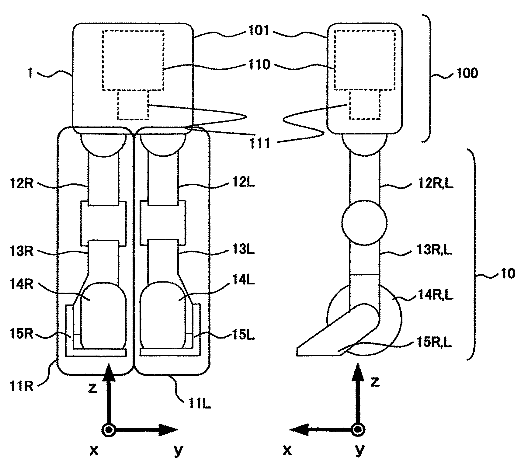
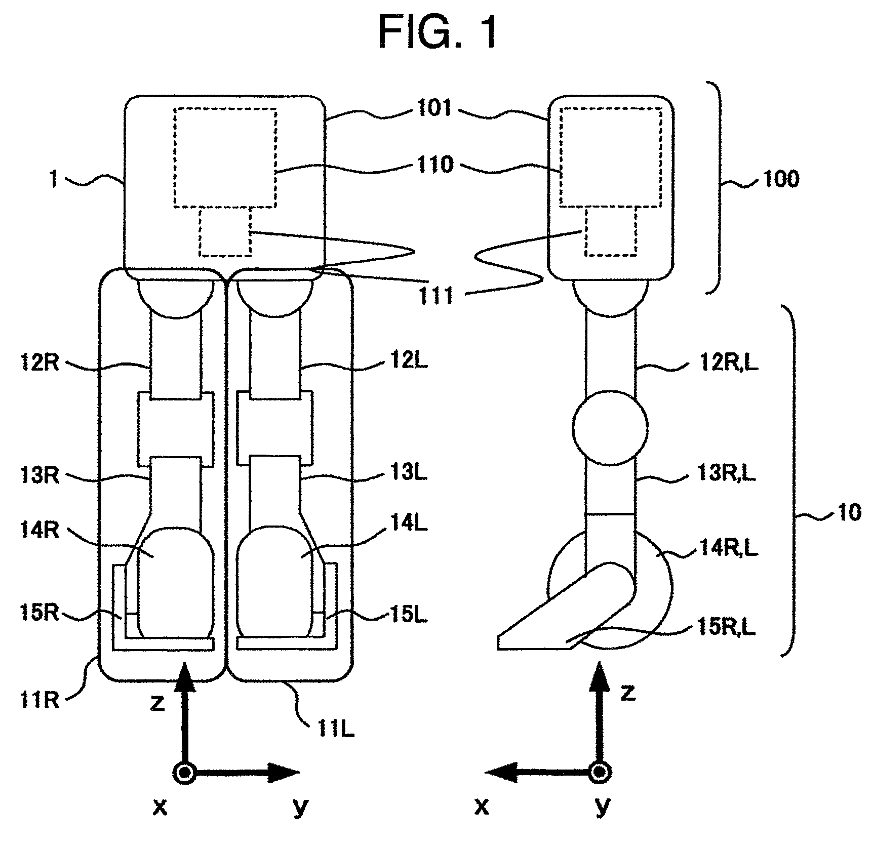
[0017]FIG. 1 schematically shows the entirety of a mobile robot, and FIG. 2 shows a joint arrangement.

[0018]The robot 1 comprises two sections of a leg section 10 and a body 100. The leg section 10 comprises right and left legs 11R and 11L, which are comprised of thigh parts 12R and 12L, lower limb parts 13R and 13L, wheels 14R and 14L, and movable supporting parts 15R and 15L, respectively. In order to distinguish the right and left parts of the leg, a letter “R” is added to the reference numerals for representing the right, while a letter “L” is added to the reference numerals for representing the left.

[0019]The body 100 is situated on the upper part of the right and left legs 11R, 11L and has a control device 110 which controls the operation of all the joints and the wheels, and an inclination angle detecting device 111 which detects an inclination angle and an angular velocity of the body with respect to the gravity direction. An X-axis is set to be in the robot front direction,...


PUM


Abstract

There is provided a high-speed and stable robot apparatus realizing stable walking by surely grounding legs having wheels even on an irregular ground surface. The mobile robot includes a body having a control device and an inclination angle detecting device which detects an inclination angle and an angular velocity, and the plurality of legs each having a thigh part and a lower limb part. The thigh part is rotatable around an X-axis, which is a front direction with respect to the body, and around a Y-axis which is a side surface direction with respect to the body. The robot comprises wheels rotatable around the Y-axis and movable supporting parts rotatable around the Y-axis and capable of being grounded on a road surface, which are provided on lower portions of the lower limb parts. The robot switches its operation according to irregularities of the road surface between coaxial two-wheeled inverted pendulum control operation of moving with the wheels without grounding the movable supporting parts while maintaining the inversion and bipedal walking control operation of walking by controlling the grounding of the wheels and the movable supporting parts on the road surface.

Description

BACKGROUND OF THE INVENTION[0001]The present invention relates to a leg-wheel type mobile robot having wheels at the tip of its leg and capable of moving on an irregular ground.[0002]As a moving system of a robot, there are moving methods based on wheels and legs. In the moving method based on legs, walking is performed by controlling the attitude of the robot on the basis of a ZMP (Zero Moment Point) as standard. The ZMP is the center of reaction force at a grounding point, and is a point on the floor surface where the moment by the reaction force becomes zero. When the robot is made to walk, it is necessary to perform control of the walking in consideration of inertia force due to the movement of the robot itself, gravitational force applied to the robot, reaction force received from the floor, and the like. When a walking pattern is generated so as to make the ZMP settled within a convex support polygon of the foot sole of the robot, the robot can be made to walk without overturn...

Claims


Application Information

Patent Timeline
Patent Type & Authority Patents(United States)
IPC IPC(8): B62D51/06
CPCB62D57/028G05D1/02
Inventor NAKAMURA, RYOSUKEAMINO, AZUSA
Owner HITACHI LTD
Why Eureka
Try Eureka