Methods and apparatuses for stabilizing the spine through an access device

a technology of access device and access device, which is applied in the field of methods and equipment for performing minimally invasive surgery, can solve the problems of reducing patient flexibility, nerve damage, scarring, pain, etc., and achieves the effect of limiting stress associated with recovery and more normal post-recovery range of motion

Active Publication Date: 2010-02-09
ZIMMER BIOMET SPINE INC
View PDF216 Cites 105 Cited by
  • Summary
  • Abstract
  • Description
  • Claims
  • Application Information

AI Technical Summary

Benefits of technology

[0008]Accordingly, there is a need in the art for minimally invasive systems and methods for stabilizing adjacent bone, e.g., vertebrae, while preserving motion therebetween. These systems and methods may advantageously provide a more normal post-recovery range of motion, and may also limit stresses associated with other stabilization procedures placed on adjacent vertebrae and intervening discs.
[0010]In another form, a method of stabilizing at least two vertebrae of the spine of a patient is provided. The method comprises coupling a first screw with a vertebra, the first screw having a first housing. A second screw having a second housing is coupled with another vertebra. A first end of a multi-layered longitudinal member is secured with the first screw. A second end of the multi-layered longitudinal member is secured with the second screw while allowing relative motion between the layers of the longitudinal member. In one variation, the first end is clamped with the first screw, substantially preventing relative motion between the layers of the longitudinal member at the first end.
[0012]In another aspect, an apparatus for retaining vertebrae of a spinal column in a desired spatial relationship is disclosed. The apparatus comprises a first fastener having a threaded shank for engaging a vertebral portion and a first housing having a first passage and a second passage having a longitudinal axis extending transverse to the first passage. The first fastener extends through an opening in the housing into the second passage. The apparatus also comprises a second fastener having a threaded shank for engaging a vertebral portion and a second housing having a first passage and a second passage having a longitudinal axis extending transverse to the first passage. The second fastener extends through an opening in the housing into the second passage. The apparatus further comprises a longitudinal member having a first end and a second end and a member axis extending therebetween. The longitudinal member comprises an array that comprises a plurality of elongated load-bearing elements. The array may be configured to be relatively inflexible along the member axis but to be relatively flexible in a direction transverse to the member axis. The array extends at least partially between the first end and the second end of the longitudinal member. The longitudinal member is configured to extend between the first passage of the first housing and the first passage of the second housing. The apparatus also comprises a first clamping device configured to be coupled with the first housing and to secure the first end of the longitudinal member to the first housing, and a second clamping device configured to be coupled with the second housing and to secure the second end of the longitudinal member to the second housing while allowing the array of elongated elements to provide a range of relative movement of the vertebrae.
[0017]In other embodiments, the longitudinal member comprises an array of elongated elements. The elements may comprise different materials, including, for example, titanium, titanium alloys, or other biocompatible materials. In some embodiments, the longitudinal member comprises a low friction material that is used to promote sliding between the elements (and / or between other portions of the longitudinal member) and to reduce wear and to substantially prevent generation of loose debris due to the relative motion within the member. A suitable low-friction material includes ultra high molecular weight polyethylene (UHMWPE). In some embodiments, the longitudinal member includes layers that alternate in composition, for example, in one embodiment the layers alternate between titanium and UHMWPE.
[0020]By coupling the multi-layered longitudinal member to the vertebrae as described, the longitudinal member acts as a spring that resists extension and flexion of the vertebrae to which the stabilization device is coupled, thereby imparting stability and natural stiffness to a diseased or damaged portion of the spine. The characteristics of the spring such as its spring rate and stiffness may be chosen by appropriately selecting the number, the length and thickness, and the material properties of the layers. The spring rate may be linear or nonlinear. In some embodiments, the spring acts as a leaf spring. In some embodiments, the longitudinal member acts as a spring in multiple dimensions, for example, in two or morel directions substantially transverse to a longitudinal axis of the member. In certain embodiments, the longitudinal member is relatively inflexible along the longitudinal axis and / or is relatively flexible in directions transverse to the longitudinal axis.

Problems solved by technology

While fusion and fixation may reduce some symptoms of disc degeneration, the elimination of motion reduces the patient's flexibility and may cause other complications.
This technique exposes nerves in the open area, which can be injured when exposed.
Consequently, open surgery carries significant risks of scarring, pain, nerve damage, and blood loss.
Unfortunately, such cannulae are usually very narrow and therefore they provide minimal space for the physician to observe the body structures and manipulate surgical instruments.

Method used


Image

  • Methods and apparatuses for stabilizing the spine through an access device
  • Methods and apparatuses for stabilizing the spine through an access device
  • Methods and apparatuses for stabilizing the spine through an access device

Examples


Embodiment Construction

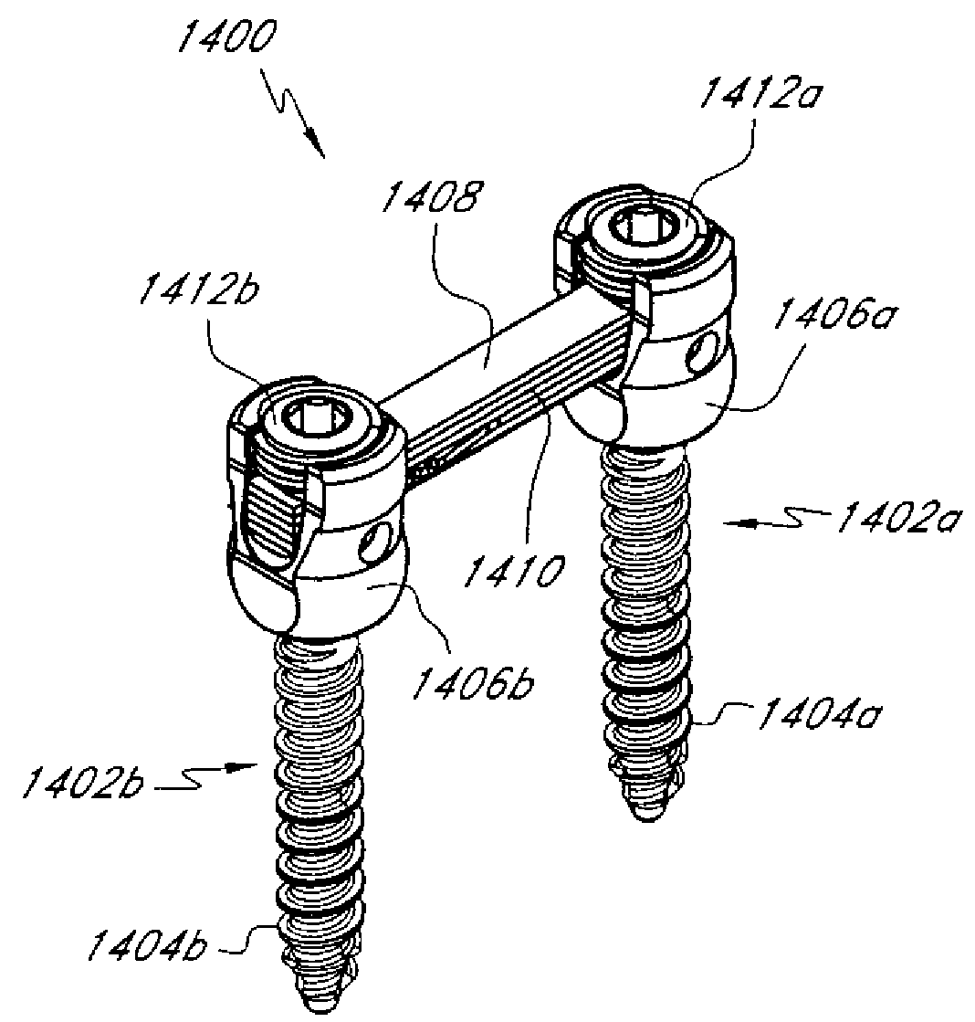
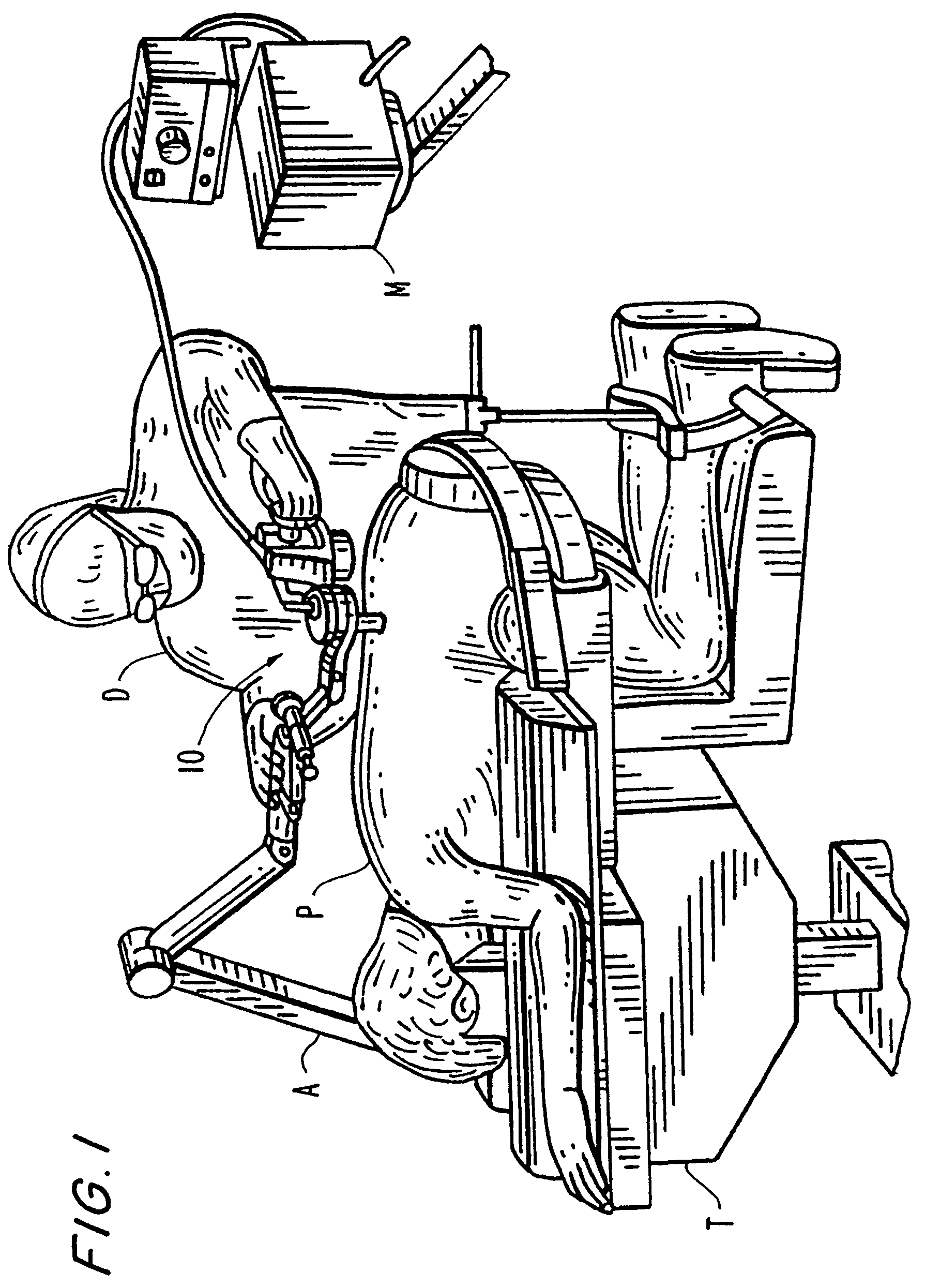
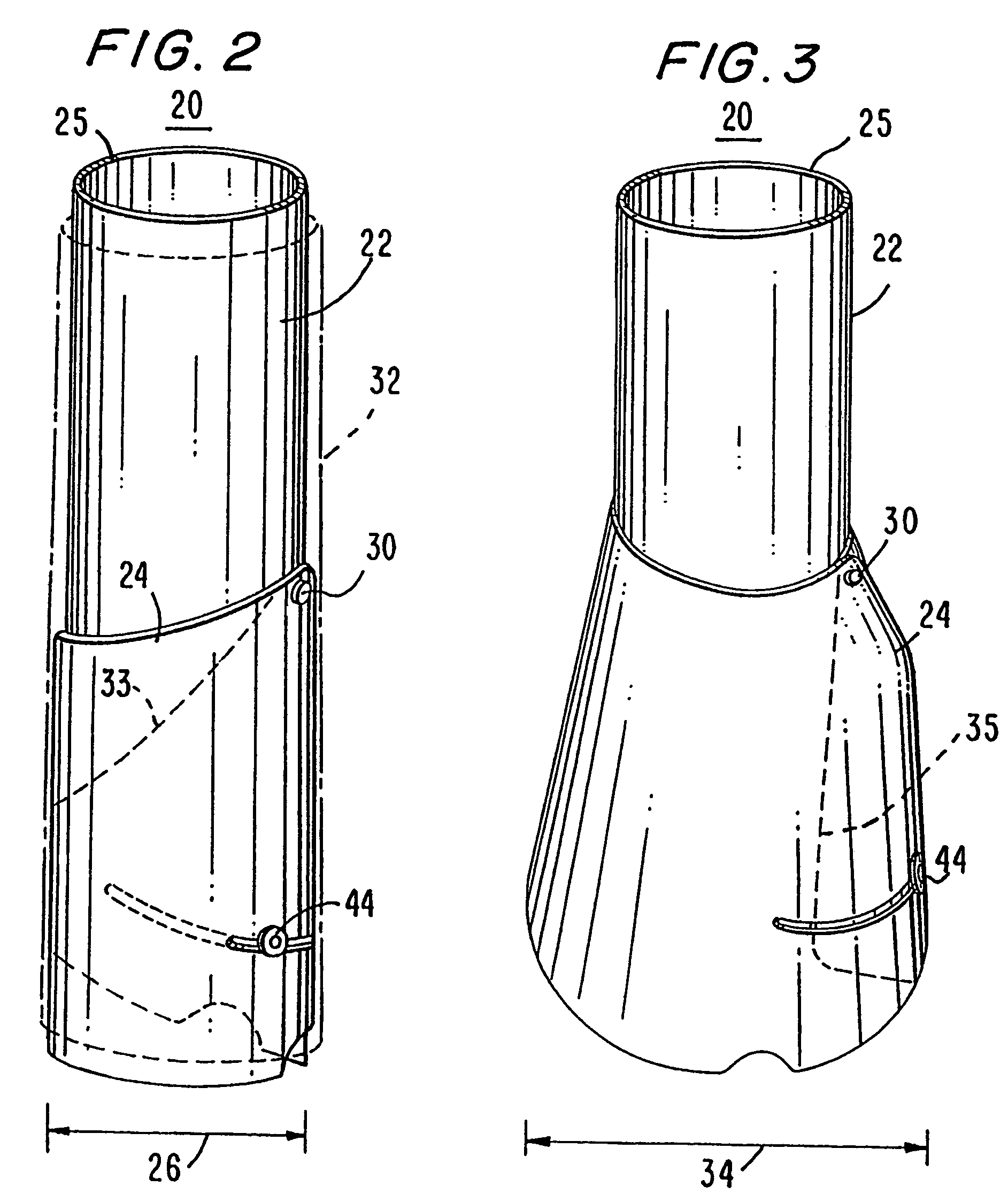
[0093]As should be understood in view of the following detailed description, this application is directed to apparatuses and methods for treating the spine of a patient through an access device, also referred to herein as an expandable conduit. More particularly, the systems described below provide access to surgical locations at or near the spine and provide a variety of tools and implants or implantable devices useful in performing treatment of the spine. For example, systems and methods are described herein that may be used to provide motion preserving stabilization of the spine, such as dynamic stabilization. Access devices and systems described herein enable these systems and methods to be practiced minimally invasively. Also, the systems described herein enable a surgeon to perform a wide variety of methods as described herein.

I. Systems for Performing Procedures at a Surgical Location

[0094]Various embodiments of apparatuses and procedures described herein will be discussed in...


PUM


Abstract

An apparatus for stabilizing vertebrae while permitting a range of motion therebetween may include first and second fasteners for engaging adjacent vertebrae and a motion preserving device that can be coupled to the first and second fasteners. The motion preserving device may include a longitudinal member that includes an array of load-bearing elements. The longitudinal member may be configured to permit the load-bearing elements to move relative to each other and / or relative to other portions of the member. In some embodiments, the longitudinal member is relatively inflexible along a longitudinal axis and relatively flexible in a direction transverse to the longitudinal axis.

Description

RELATED APPLICATION[0001]This application claims the benefit under 35 U.S.C. § 119(e) of U.S. Provisional Patent Application No. 60 / 721,580, filed on Sep. 27, 2005, entitled “METHODS AND APPARATUSES FOR STABILIZING THE SPINE THROUGH AN ACCESS DEVICE,” which is hereby incorporated by reference herein in its entirety.BACKGROUND OF THE DISCLOSURE[0002]1. Field of the Disclosure[0003]This application relates generally to methods and apparatuses for performing minimally invasive surgery, and more particularly to methods and apparatuses for performing procedures for stabilizing adjacent bones while preserving motion therebetween.[0004]2. Description of the Related Art[0005]In the past, patients suffering from degenerative spine conditions, such as progressive degeneration of intervertebral discs, have been treated by various techniques. For example, fixation and fusion are two procedures that are sometimes performed in combination to address degeneration of the intervertebral discs. Fusio...

Claims


Application Information

Patent Timeline
Patent Type & Authority Patents(United States)
IPC IPC(8): A61B17/56
CPCA61B17/7023A61B17/7025A61B17/7026A61B17/7044A61B17/7059A61B17/70A61B17/1757A61B17/7091A61B17/7004A61B17/7005A61B17/7007A61B17/701A61B17/7032A61B17/7037A61B17/7064A61B2017/00261A61B2017/0256A61F2/4405A61B17/7079A61B17/7082A61B17/7085
Inventor SHLUZAS, ALAN E.
Owner ZIMMER BIOMET SPINE INC
Why Eureka
Try Eureka