Part for protecting the leading edge of a blade

a technology for leading edges and blades, applied in the field of aviation, can solve the problems of insufficient strength and difficult formation of alloys, and achieve the effect of improving mechanical strength and facilitating the attachment of said layer to the blad

Active Publication Date: 2006-12-07
SN DETUDE & DE CONSTR DE MOTEURS DAVIATION S N E C M A
View PDF14 Cites 28 Cited by
  • Summary
  • Abstract
  • Description
  • Claims
  • Application Information

AI Technical Summary

Benefits of technology

[0010] In a particular embodiment of the invention, the part comprises at least two layers including an outer layer and an inner layer, the outer layer being made of said reinforced aluminum alloy and the inner layer being made of an aluminum alloy that is optionally reinforced with SiC particles, the content of SiC particles within the layers increasing on going from the inner layer towards the outer layer. Thus, mechanical strength increases going from the inside towards the outside of the part.
[0011] Using an aluminum alloy that is reinforced little or not at all

Problems solved by technology

At below 15% SiC, this strength is not sufficient.

Method used


Image

  • Part for protecting the leading edge of a blade
  • Part for protecting the leading edge of a blade

Examples


Embodiment Construction

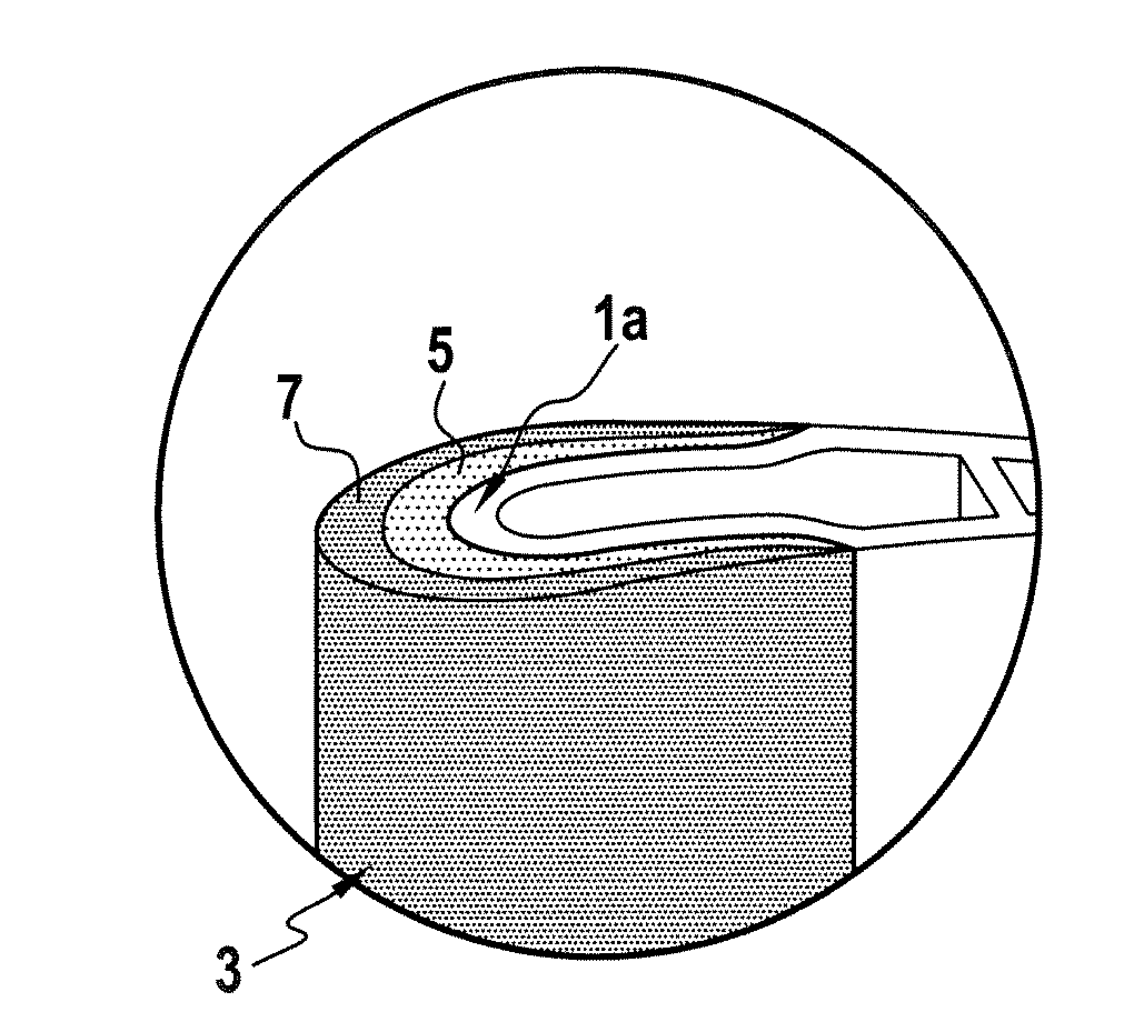
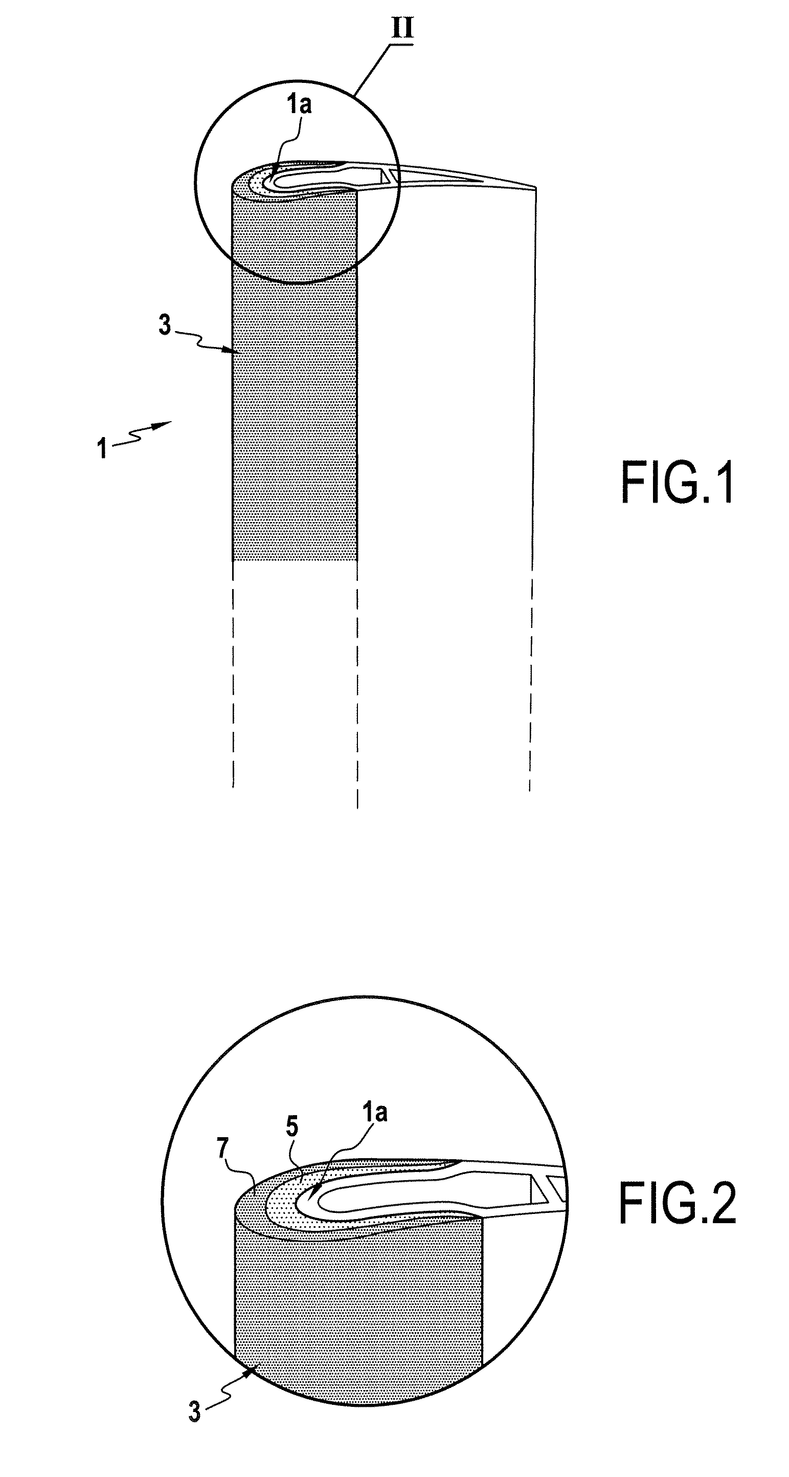
[0016]FIGS. 1 and 2 show the airfoil portion of a turbomachine blade 1. The leading edge 1a of the blade 1 is covered by a protection part 3 of the invention.

[0017] The protection part 3 is substantially U-shaped in section, enabling it to be placed astride the leading edge 1a of the blade 1. The part 3 is made up of two layers, an inner layer 5 and an outer layer 7. The outer layer 7 is of aluminum alloy reinforced with particles of SiC, while the inner layer 5 is made of the same aluminum alloy, but is not reinforced with SiC. Preferably, for aviation applications, an aluminum alloy of the 7000 series is selected.

[0018] Naturally, the protection part may have more than two layers, with the content of SiC particles in each layer increasing going from the inside towards the outside. Thus, in an embodiment not shown, the protection part is made of four layers C1, C2, C3, and C4 with the SiC content in the inner layer C1 being zero, about 10% by weight in C2, about 20% in C3, and ab...


PUM

PropertyMeasurementUnit
Fractionaaaaaaaaaa
Percent by massaaaaaaaaaa

Abstract

A protection part comprising at least two layers including an outer layer and an inner layer has its outer layer made of an aluminum alloy that is reinforced with particles of SiC, the SiC particle content in said alloy lying in the range 15% to 40% by weight, while the inner layer is made of an aluminum alloy that is optionally reinforced with SiC particles, the SiC particle content within the layers increasing from the inner layer towards the outer layer. The part is for use in protecting the leading edge of a blade, in particular a blade or vane in a turbomachine, a helicopter blade, or a propeller blade.

Description

[0001] The invention relates to a protection part used, for example, for protecting the leading edge of a blade in a turbomachine, a propeller blade, or a helicopter blade. BACKGROUND OF THE INVENTION [0002] In the field of aviation, and more particularly in the field of aircraft turbojets, reducing the weight of the component parts of the turbojet is a perpetual preoccupation. [0003] Thus, blades have been developed for turbojet fans or stators that are made of an organic-matrix composite material (e.g. based on cyanate-ester, bismaleimide, or epoxy resin), such that the blades are lighter in weight than metal blades. [0004] Nevertheless, the leading edges of such blades need to be protected against erosion and possible impacts by means of a protection part fitted to the leading edge. [0005] Until now, such protection parts have been made of titanium alloy of the TA6V type. That solution is technically viable, since the alloy presents good resistance to erosion and to impacts. Neve...

Claims


Application Information

Patent Timeline
IPC IPC(8): B32B9/00
CPCB23P15/04F01D5/147F01D5/28Y02T50/672Y10T428/12458F05D2300/2261F05D2300/173Y10T428/30Y10T428/12764F05D2300/702F04D29/324F05D2240/303Y10T428/31678Y02T50/60
Inventor BERNARD, JACQUESMONS, CLAUDE MARCELPESLERBE, ISABELLETHOMAS, THIERRY
Owner SN DETUDE & DE CONSTR DE MOTEURS DAVIATION S N E C M A
Why Eureka
Try Eureka