Process and device for machining by windowing of non-deformable thin panels

a technology of non-deformable thin panels and windowing, which is applied in the direction of computer control, program control, instruments, etc., can solve the problem that the positioning according to just isostatic principles is not sufficient to ensure the effect of the

Active Publication Date: 2007-01-30
AIRBUS OPERATIONS (SAS)
View PDF20 Cites 29 Cited by
  • Summary
  • Abstract
  • Description
  • Claims
  • Application Information

AI Technical Summary

Benefits of technology

[0014]The alignment on a bed of suction cups is a solution, which, by limiting the number of support point, limits the degree of hyperstatism and consequently the internal fastening stresses. It is effective for all routing operations. On the other hand, the act of performing machining in the thickness direction requires a significant increase in the density of the supports. For example, if routing operations are satisfied with a space between supports of about 500 mm, machining operations for recesses require a space between supports of less than 150 mm. Consequently, this solution produces a similar result in terms of the quality of orientation compared with that obtained on rigid tools.
[0016]The present invention seeks to mitigate the disadvantages of conventional alignment methods and proposes a machining process that allows a non-deformable panel, e.g., a molded panel to be held in position without stressing it, with alignment of its external convex surface based on its theoretical definition (internal surface) for purposes of the mechanical performance of precision machining operations such as those enumerated above.
[0026]a means for holding one of the surfaces of the panel in position over a predetermined extent without introducing hyperstatism,
[0045]The process disclosed in this invention allows for significant improvements in comparison with existing processes, in particular in the production of recesses requiring a depth precision of less than 0.2 mm.

Problems solved by technology

Consequently, its positioning according to just isostatic principles is not sufficient to ensure a suitable alignment of the panel: It should be “rigidified” by supporting it with many more points than are necessary for its strict orientation in space.

Method used


Image

  • Process and device for machining by windowing of non-deformable thin panels
  • Process and device for machining by windowing of non-deformable thin panels
  • Process and device for machining by windowing of non-deformable thin panels

Examples


Embodiment Construction

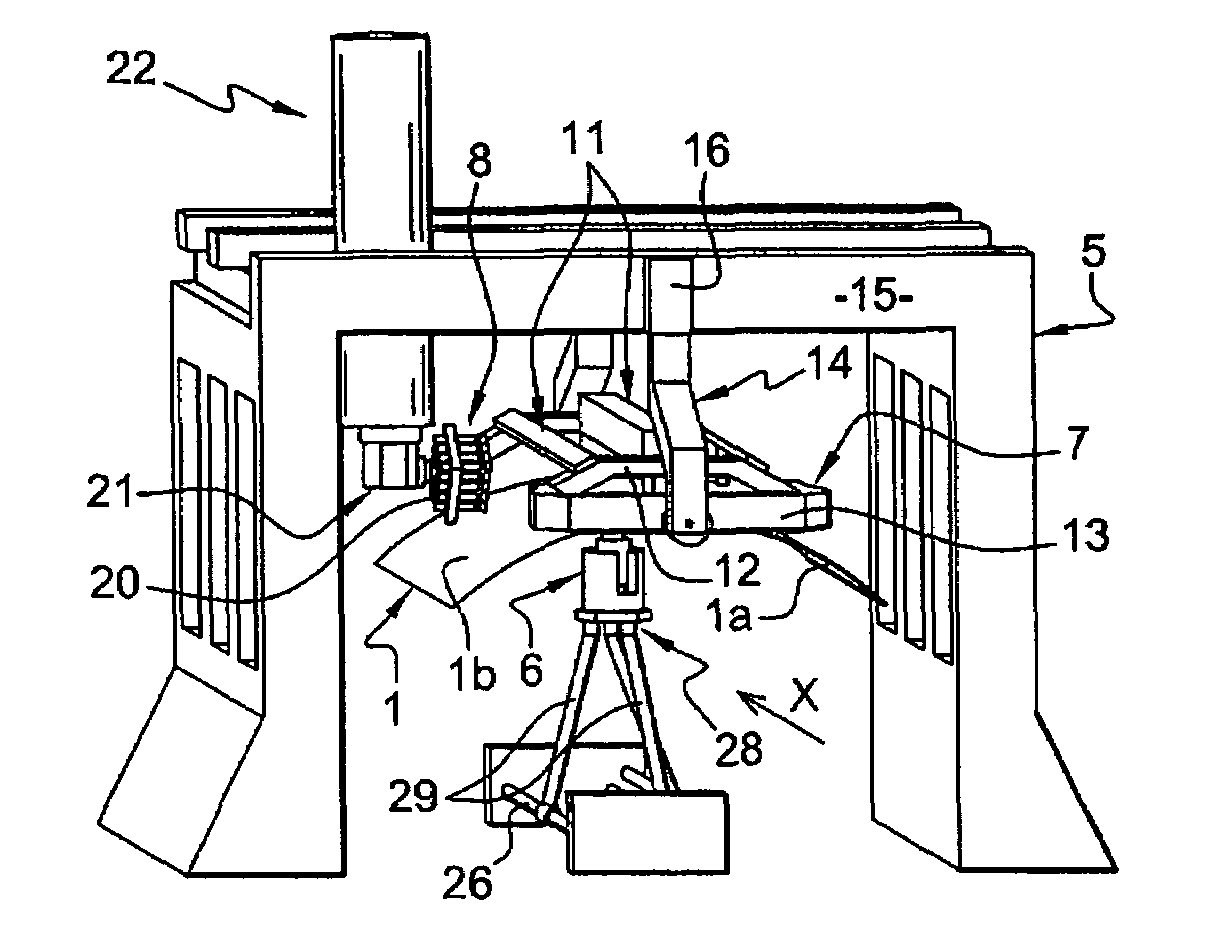
[0069]FIG. 1 illustrates schematically the principle of isostatic positioning of a panel 1 having a double curvature.

[0070]Panel 1 is a flexible, thin, non-deformable panel, e.g., a metal panel for covering an aircraft fuselage and has been shaped beforehand in a known manner by drawing on a convex mold.

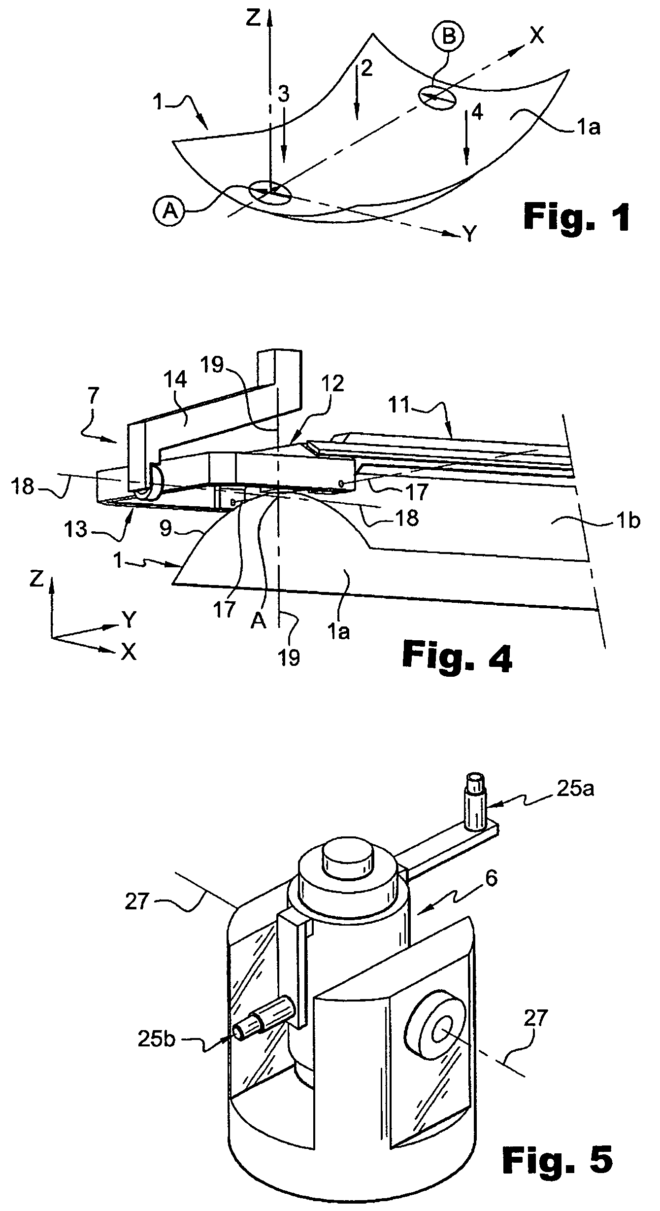
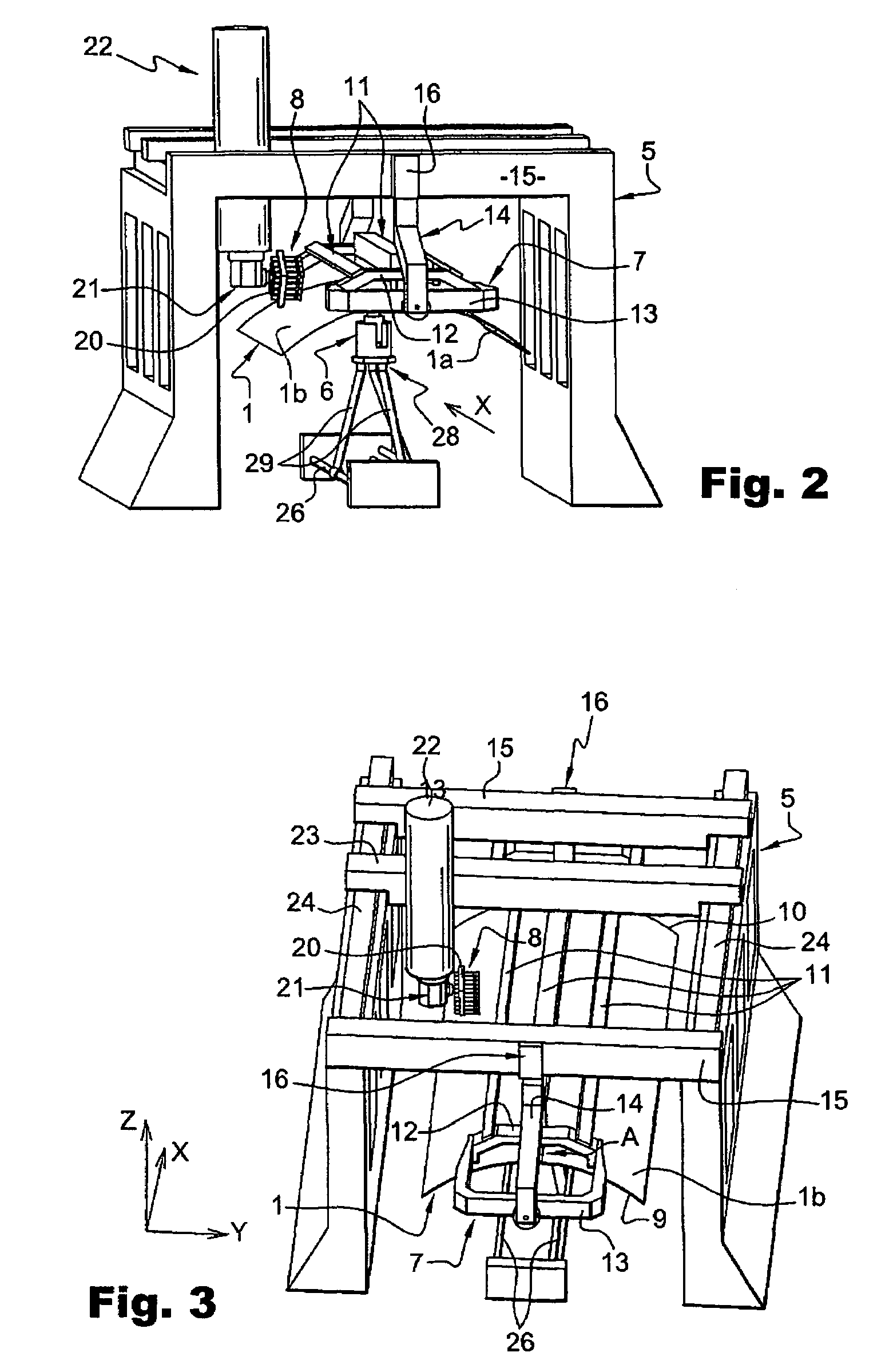
[0071]As described above, such a panel 1 displays variations in thickness over its entire surface. The geometrically known surface of panel 1 is the concave internal surface 1a, which was in contact with the drawing mold. The reference surface is the opposite surface 1b (FIG. 2 and the following figures) and is convex, corresponding to the external wall of the fuselage that will be produced by employing the panel.

[0072]Since panel 1 is machined on its geometrically known surface 1a, whereas the reference surface is surface 1b and the thickness of the panel has variations which are not known, this obviously presents a machining problem, particularly if one wants to create recesses who...


PUM

PropertyMeasurementUnit
thicknessesaaaaaaaaaa
degrees of freedomaaaaaaaaaa
diameteraaaaaaaaaa

Abstract

An apparatus and method for machining of thin panels, in particular, panels having a complex shape, specifically non-deformable panels, in which the panel to be machined is placed beforehand in an isostatic position, characterized by: one defines one or more areas of a predetermined extent for purposes of machining, named machining windows, in the area of the panel to be machined; and perpendicular to each machining window; one of surfaces of panel is held in position without introducing positioning hyperstatism; the actual shape of the aforementioned surface is measured; the desired machining operation is performed on the opposite surface by taking the aforementioned measured surface as a reference; and the aforementioned surface is released.

Description

RELATED APPLICATION[0001]The present application claims priority to French Application No. 04 1276 filed Feb. 10, 2004.TECHNICAL FIELD[0002]The present invention concerns machining through the removal of material from fine, flexible parts, in particular of a complex shape, such as panels of a non-deformable shape, e.g., aircraft fuselage panels. In particular the invention relates to a machining process and apparatus that is applicable to metallic panel types with or without stiffeners, composite panels, or “sandwich” type panels, on which machining operations affecting their thickness are to be performed, such as surfacing or the formation of recesses or cells, or routing or drilling operations.BACKGROUND OF THE INVENTION[0003]The panels disclosed in this invention are panels having a double curvature, mainly located at the front of aircraft. These panels, generally made of a light alloy, have thicknesses ranging from 1 to 12 mm depending on the aircraft and the components of the p...

Claims


Application Information

Patent Timeline
Patent Type & Authority Patents(United States)
IPC IPC(8): B23C3/16B25B11/00B64C1/12B64F5/00G05B19/401G05B19/408
CPCB23Q1/035B25B11/005B64C1/12B64F5/0009G05B19/401G05B19/4083B23Q1/766Y10T409/309016G05B2219/36503G05B2219/45174G05B2219/49136Y10T409/30756Y10T409/308624Y10T409/30868Y10T409/30896Y10T409/307896Y10T409/303752B64F5/10
Inventor HAMANN, JEAN-CHRISTOPHE
Owner AIRBUS OPERATIONS (SAS)
Why Eureka
Try Eureka