Locking system for drawers

a locking system and drawer technology, applied in the field of drawer locking systems, can solve the problems of affecting the security of the file cabinet, affecting the file cabinet, and the locking system of the file cabinet is also susceptible to improper locking by the user, so as to increase the security of items stored

Active Publication Date: 2010-02-23
COMPX INTERNATIONAL
View PDF19 Cites 1 Cited by
  • Summary
  • Abstract
  • Description
  • Claims
  • Application Information

AI Technical Summary

Benefits of technology

[0010]In a broader present object, drawer locking system methodology and corresponding apparatus are provided for improved locking functionality, particularly across the width of a drawer. In some present embodiments, it is also a present object to provide such improved functionality generally regardless of any drawer misalignment over time.
[0012]The present locking system in certain embodiments thereof may employ a lock that engages a drive actuator to move a lock bar into a desired position for locking one or more drawers of such an exemplary file cabinet. A follower or slave actuator may also be provided and may through use of a shaft be placed into communication with the drive actuator. The follower or slave actuator may be used to move a lock bar into a desired position for locking one or more drawers of the file cabinet. In such embodiments, it is also a present object that the main or drive actuator (primary actuator) and slave or follower actuator (secondary actuator) may be respectively positioned in order to lock opposite ends of a drawer, to provide increased security of items stored in the file cabinet.
[0016]A further exemplary embodiment of the locking system exists as substantially described above in which the shaft that connects the drive (primary or main) actuator and the slave (secondary or follower) actuator is positioned in close proximity to a top panel of the file cabinet. Such positioning eliminates or minimizes interference between the shaft and items, such as files, that may be stored in the drawers of the file cabinet. Similarly, a relatively lower profile or projection of the lock features of the present subject matter relative to a drawer and / or filing cabinet with which the subject-matter is used helps minimize interference of such physical elements with their environment, such as persons moving around the filing cabinet or files or other materials being moved in the vicinity of the filing cabinet.

Problems solved by technology

Although the side of the drawer with the lock may be prevented from being opened, the opposite side of the drawer may be able to be opened a large distance, thus compromising the security of the file cabinet.
Such arrangement may be problematic in that a shaft used to communicate rotation of the lock to the actuator and / or the lock bar may interfere with files placed into the file cabinet.
Locking systems on file cabinets are also susceptible to improper locking by the user.
Upon closing the drawer, the lock is then not capable of being placed into the locked position in order to lock the file cabinet.

Method used


Image

  • Locking system for drawers
  • Locking system for drawers
  • Locking system for drawers

Examples


third embodiment

[0051]Reference will now be made in detail to embodiments of the present subject matter, one or more examples of which are illustrated in the drawings. Each example is provided by way of explanation of the present subject matter, and not meant as a limitation of the present subject matter. For example, features illustrated or described as part of one embodiment can be used with another embodiment to yield still a It is intended that the present subject matter include these and other modifications and variations.

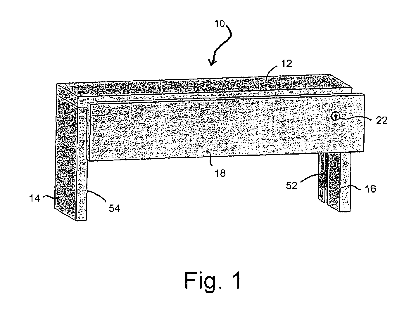
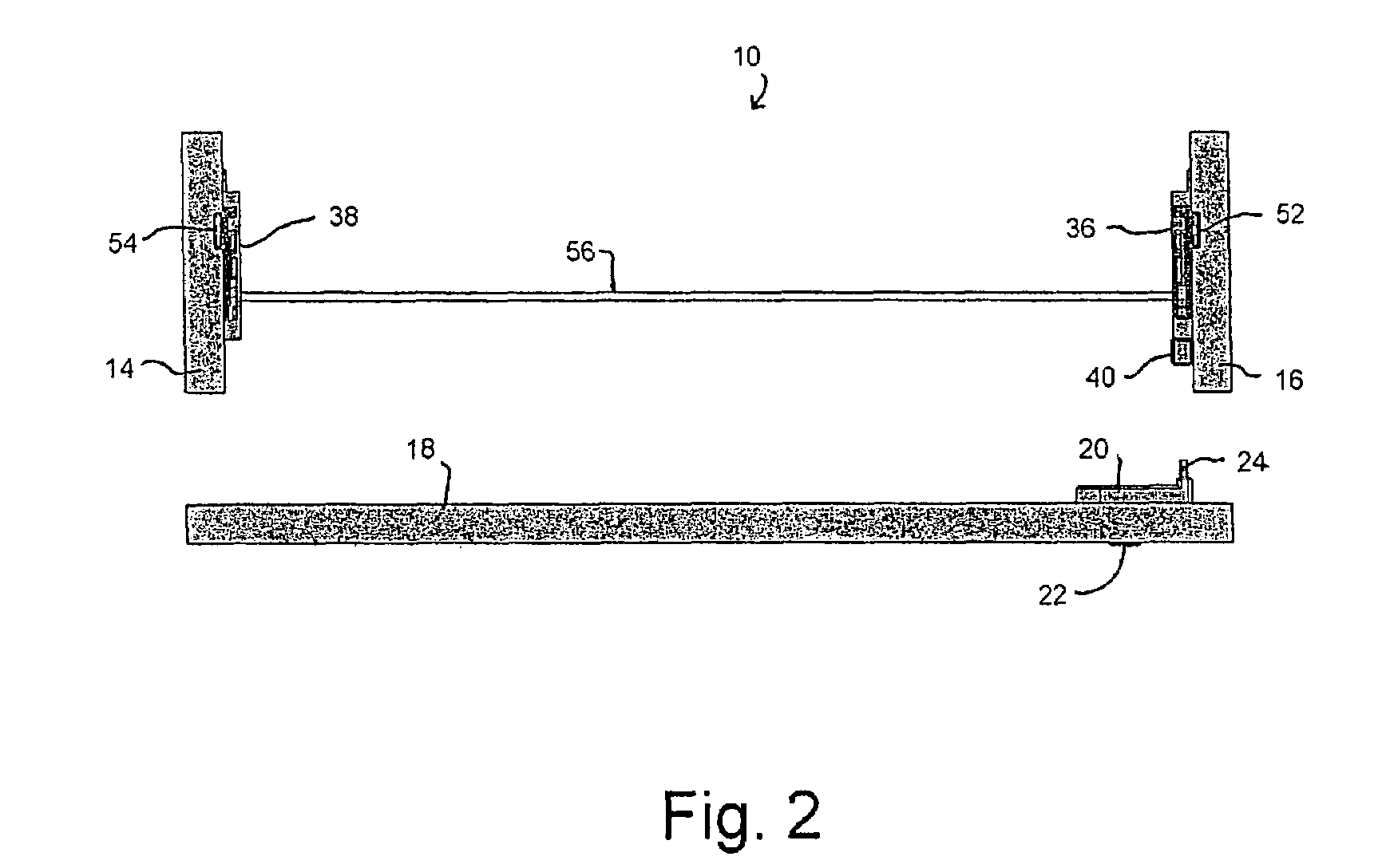
[0052]In general, the illustrations of FIGS. 1-7, inclusive, relate to a first present exemplary embodiment of the present subject matter, while the illustrations of FIGS. 8-14, inclusive, relate to a second present exemplary embodiment of the present subject matter. Repeat use of reference characters in the respective embodiments of the respective groups of drawings is intended to represent the same or analogous features or elements of the present subject matter, with only ...

first exemplary embodiment

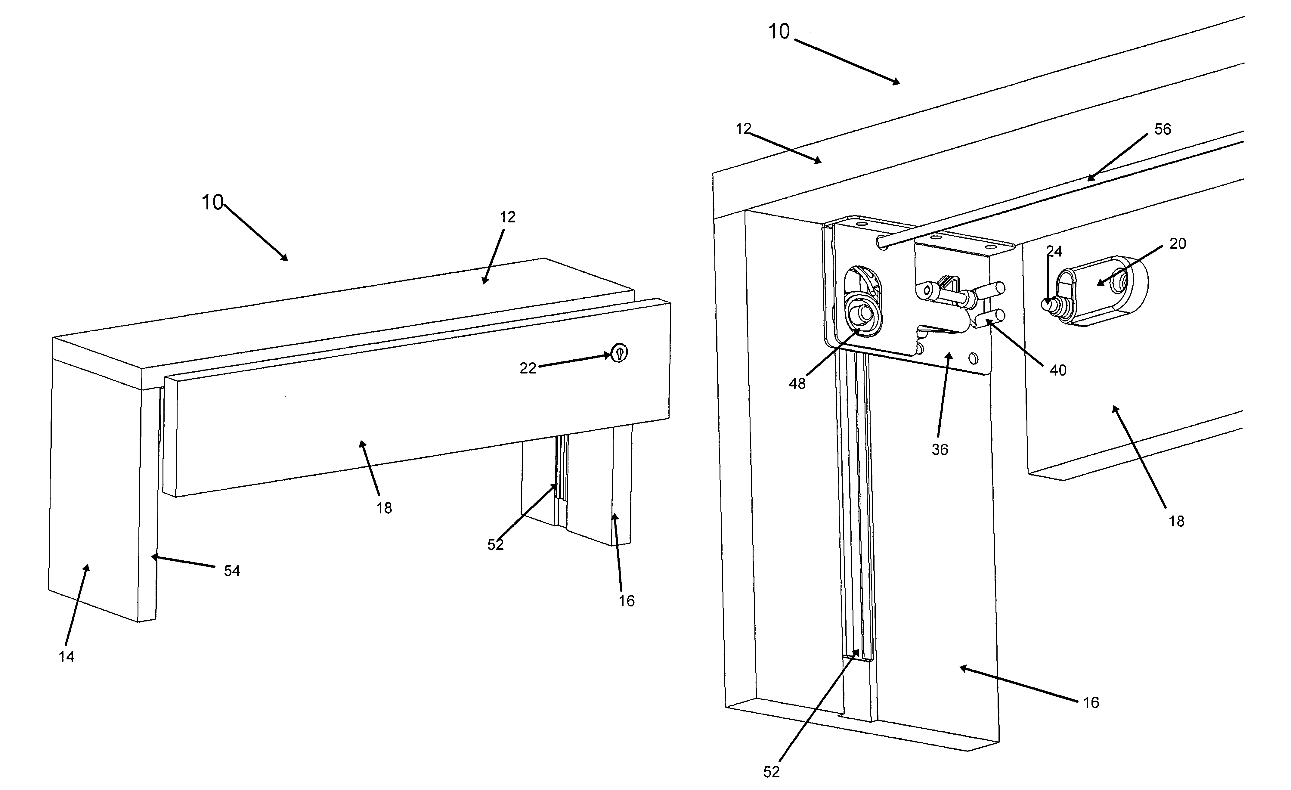
[0066]Shaft 56 is shown as being in close proximity to exemplary top panel 12. In accordance with the first exemplary embodiment, shaft 56 may be located up to and including 9 / 32 inches from the top panel 12. In accordance with other exemplary embodiments, the distance between the top panel 12 and the shaft 56 may be from ⅛ inch to ½ inch. By placing shaft 56 in close proximity to the top panel 12, files that are located in the drawer 18 may have ample room for clearance and will not contact or otherwise interfere with shaft 56. As such, larger items may be stored in the drawer 18 and may be less susceptible to interference, thus facilitating easier closing and opening of the drawer 18 and less damage to the items stored therein. Similarly, a relatively lower profile or projection of the lock features of the present subject matter relative to a drawer and / or filing cabinet with which the subject matter is used helps minimize interference of such physical elements with their environm...


PUM


Abstract

A locking system for drawers may include a lock with a lock driver that is configured for engaging a drive actuator. The drive actuator may have a lock bar slider in communication with a lock bar. A slave actuator may also be provided in communication with the drive actuator through a shaft. The drive actuator and slave actuator may be respectively positioned so as to lock opposite ends of a drawer. The locking system may also provide the lock with a lock driver that is prevented from being moved into a locked position when the drawer is opened. One of several different resulting arrangements prevents unintentional or inadvertent locking until the drawer is placed into engagement with a drive actuator.

Description

PRIORITY CLAIM[0001]This application claims the benefit of previously filed U.S. Provisional Patent Application entitled “LOCKING SYSTEM FOR DRAWERS,” assigned U.S. Ser. No. 60 / 702,550, filed Jul. 26, 2005, and which is incorporated herein by reference for all purposes.BACKGROUND OF THE INVENTION[0002]Drawers found in chests, stands, cabinets, furniture and the like typically employ locking mechanisms for security. For example, lateral file cabinets generally have a locking mechanism for use in locking one or more drawers in order to safely store files therein. Some locking mechanisms employ a lock that is attached to a drawer of the file cabinet and that is actuated by a user through a key. The lock engages an actuator located in the file cabinet when the drawer of the file cabinet is closed. The actuator is in turn connected to a lock bar that slides vertically with respect to the file cabinet.[0003]Rotational motion created by turning the key in the lock is thus transferred into ...

Claims


Application Information

Patent Timeline
Patent Type & Authority Patents(United States)
IPC IPC(8): E05B65/46E05B65/462
CPCE05B65/46E05B65/462
Inventor WALLA, GREGG W.
Owner COMPX INTERNATIONAL
Why Eureka
Try Eureka