Magnetic racetrack with current-controlled motion of domain walls within an undulating energy landscape

a technology of current-controlled motion and domain walls, applied in static storage, digital storage, instruments, etc., can solve the problems of parasitic and inconvenient maintenance of domain walls, and the inability of domain walls to resist thermal fluctuations

Inactive Publication Date: 2010-02-23
IBM CORP
View PDF16 Cites 18 Cited by
  • Summary
  • Abstract
  • Description
  • Claims
  • Application Information

AI Technical Summary

Problems solved by technology

In an entirely uniform, smooth and magnetically homogeneous track the energy of a domain wall does not depend on its position along the track and thus a domain wall may not be stable against thermal fluctuations and parasitic magnetic fields, e.g., those from nearby domain walls in the same or adjacent tracks.

Method used


Image

  • Magnetic racetrack with current-controlled motion of domain walls within an undulating energy landscape
  • Magnetic racetrack with current-controlled motion of domain walls within an undulating energy landscape
  • Magnetic racetrack with current-controlled motion of domain walls within an undulating energy landscape

Examples


Embodiment Construction

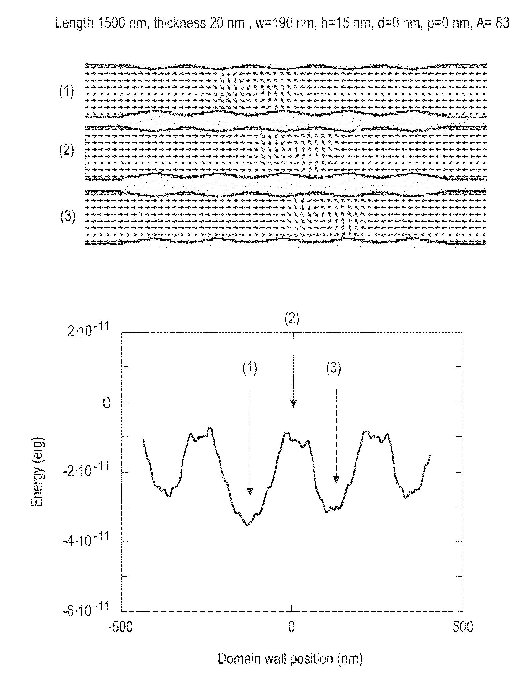
[0041]The energy landscape of a domain wall (DW) propagating along a prior art racetrack is shown in FIG. 3A. A succession of local minima of the DW's energy corresponds to sites where the track has been engineered to result in pinning of the DW when at rest. In the prior art, these pinning sites are separated by regions of the racetrack in which the energy of the DW is constant, i.e., the racetrack includes segments of constant size and of uniform material composition and hence a given domain wall has constant energy throughout these segments (see FIG. 3A). There may be extrinsic defects in these segments such as edge and surface roughness which may add small random fluctuations to the energy profile. For operation of prior art racetrack devices, these fluctuations are sufficiently small that they do not pin the DWs between the engineered DW pinning sites.

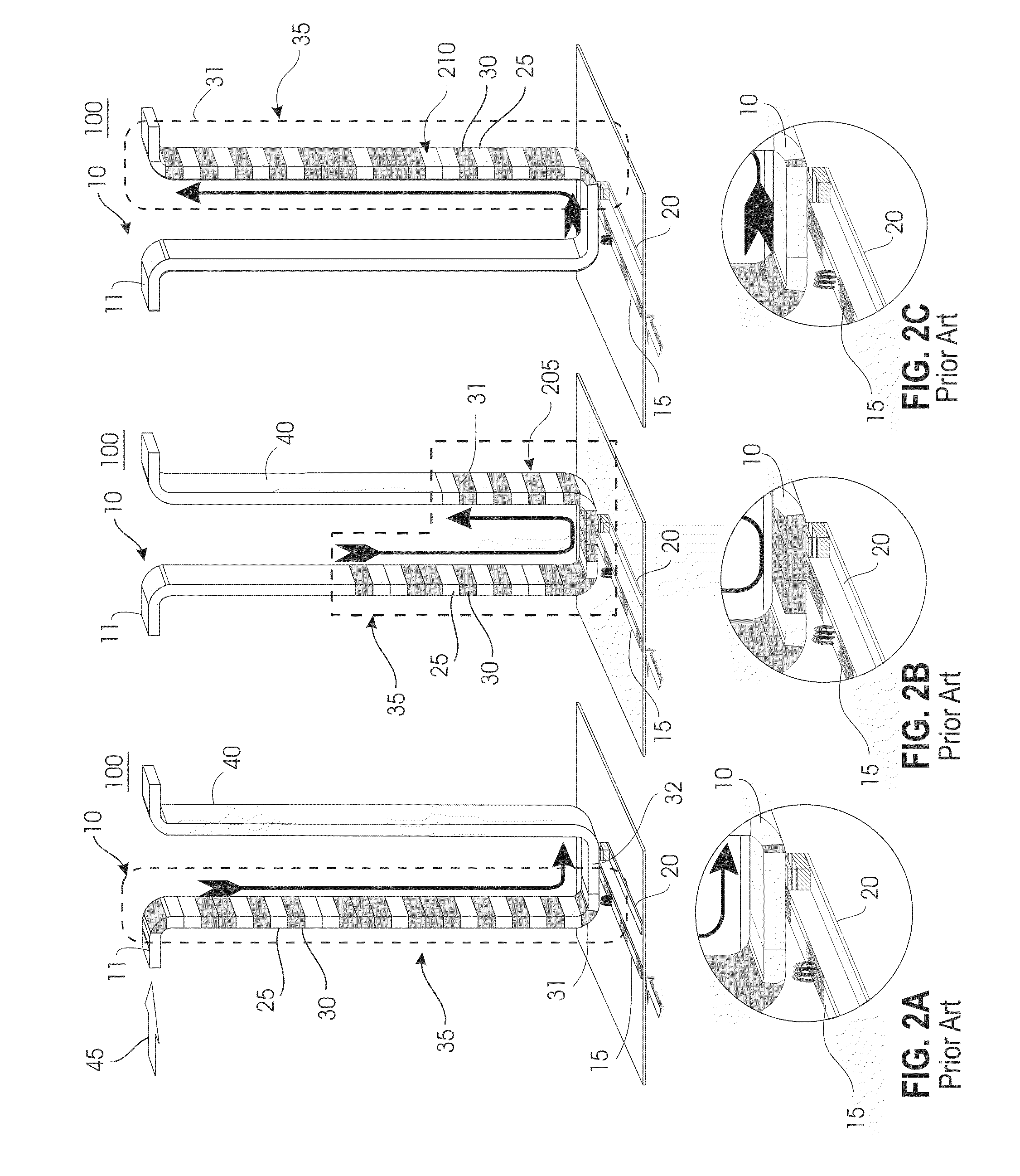
[0042]Short current pulses are used to drive each DW from one current pinning site to the next adjacent site in one direction or...


PUM


Abstract

A method for use with a magnetic racetrack device includes placing domain walls having a first structure and domain walls having a second, different structure along the racetrack at stable positions corresponding to different regions within the device. The domain walls having the first structure and the domain walls having the second structure occupy alternating positions along the racetrack. A current pulse is applied to the racetrack, so that each of the domain walls moves to an adjacent region. This results in a transformation of the domain walls having the first structure into domain walls having the second structure, and vice versa. The first structure may be a vortex structure and the second structure may be a transverse structure.

Description

[0001]This application is a divisional of Applicants' copending U.S. application Ser. No. 12 / 197,155 filed Aug. 22, 2008 and entitled “Magnetic racetrack with current-controlled motion of domain walls within an undulating energy landscape”, which is hereby incorporated by reference.[0002]This invention was made with Government support under Contract No. H94003-05-2-0505 awarded by the U.S. Department of Defense. The Government has certain rights in the invention.TECHNICAL FIELD[0003]The present invention relates to memory storage systems, and particularly to a memory storage system that uses current to move magnetic domain walls across read and write devices, allowing data to be stored in, and read out of, domains or domain walls in a magnetic racetrack.BACKGROUND[0004]Racetrack memory devices are gaining interest as high-density storage devices. These devices are disclosed, for example, in U.S. Pat. No. 6,834,005 titled “Shiftable magnetic register and method of using the same” iss...

Claims


Application Information

Patent Timeline
Patent Type & Authority Patents(United States)
IPC IPC(8): G11C19/00
CPCG11C11/14G11C19/0841Y10S977/933G11C11/161G11C11/1673G11C11/1675G11C11/15
Inventor MORIYA, RAIPARKIN, STUARTTHOMAS, LUC
Owner IBM CORP
Why Eureka
Try Eureka