Acoustin structure of seat back

a seat back and acoustic technology, applied in the field of sound systems, can solve the problems of not being able to enjoy music satisfactorily, not being able to impart sound through, and avoiding conventional etc., to achieve the effect of improving the acoustic structure of seats, increasing the cushioning support touch, and high air permeability

Inactive Publication Date: 2010-02-23
TACHI S CO LTD
View PDF4 Cites 37 Cited by
  • Summary
  • Abstract
  • Description
  • Claims
  • Application Information

AI Technical Summary

Benefits of technology

[0010]In view of the above-stated drawbacks, it is a purpose of the present invention to provide an improved acoustic structure of seat back which allows for deep and wide expansion of a sound emitted from speakers in seat back to an entire area of back portion of a user (or a seat occupant) which is to rest on the seat back, thereby giving the occupant a splendid impression as if the music was actually and vividly played, while providing a far increased cushiony support touch to the user's back portion, with a high air permeability.

Problems solved by technology

The foregoing conventional acoustic structure of seat has, however, been found defective in that:
(i) the cushion material used is a foam padding material formed from urethane foam for optimal cushioning effect, but, is not suited for imparting the sound therethrough because of its property of absorbing sound and degrading acoustic effect, and
(ii) the sound emitted from each speaker is limited to a region which is substantially compassed by a diameter of the speaker itself, and such limited range of sound emission is directed to the back of an occupant on the seat, as a result of which, the occupant can not enjoy the music satisfactorily, and can not feel such vivid sound as if the music was performed in a real concert hall, neither, due to the foregoing sound absorption by the foam cushion material.
However, such exposed speakers interfere with the occupant's movement, thus impairing a comfortable seating condition of the seat, and further, the range of sound emission from such exposed speaker arrangement is limited to a narrow space around the seat occupant, so that the occupant can not fully enjoy the sound or music with his or her body.

Method used


Image

  • Acoustin structure of seat back
  • Acoustin structure of seat back
  • Acoustin structure of seat back

Examples


Embodiment Construction

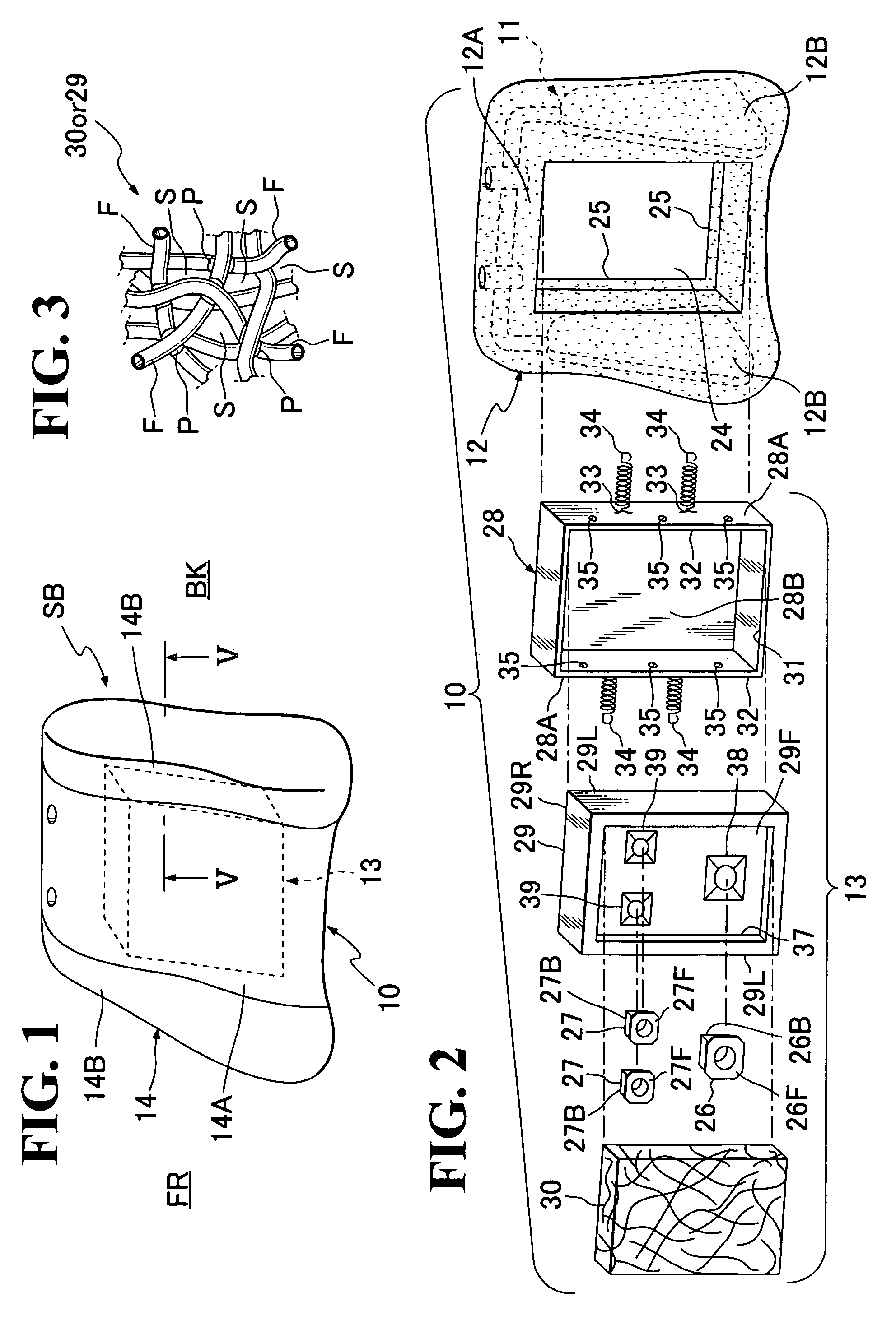
[0038]Referring to FIGS. 1 through 14, there are illustrated exemplary modes of acoustic structure of seat back of automotive seat in accordance with the present invention.

[0039]Reference numeral (10) indicates a generic mode of acoustic structure of seat back of automotive seat in accordance with the present invention, which commonly covers the non-distinctive exemplary embodiments of the seat-back acoustic structure which are shown in FIGS. 1 to 14. Designation (SB) represents an exemplary seat back used in the present invention.

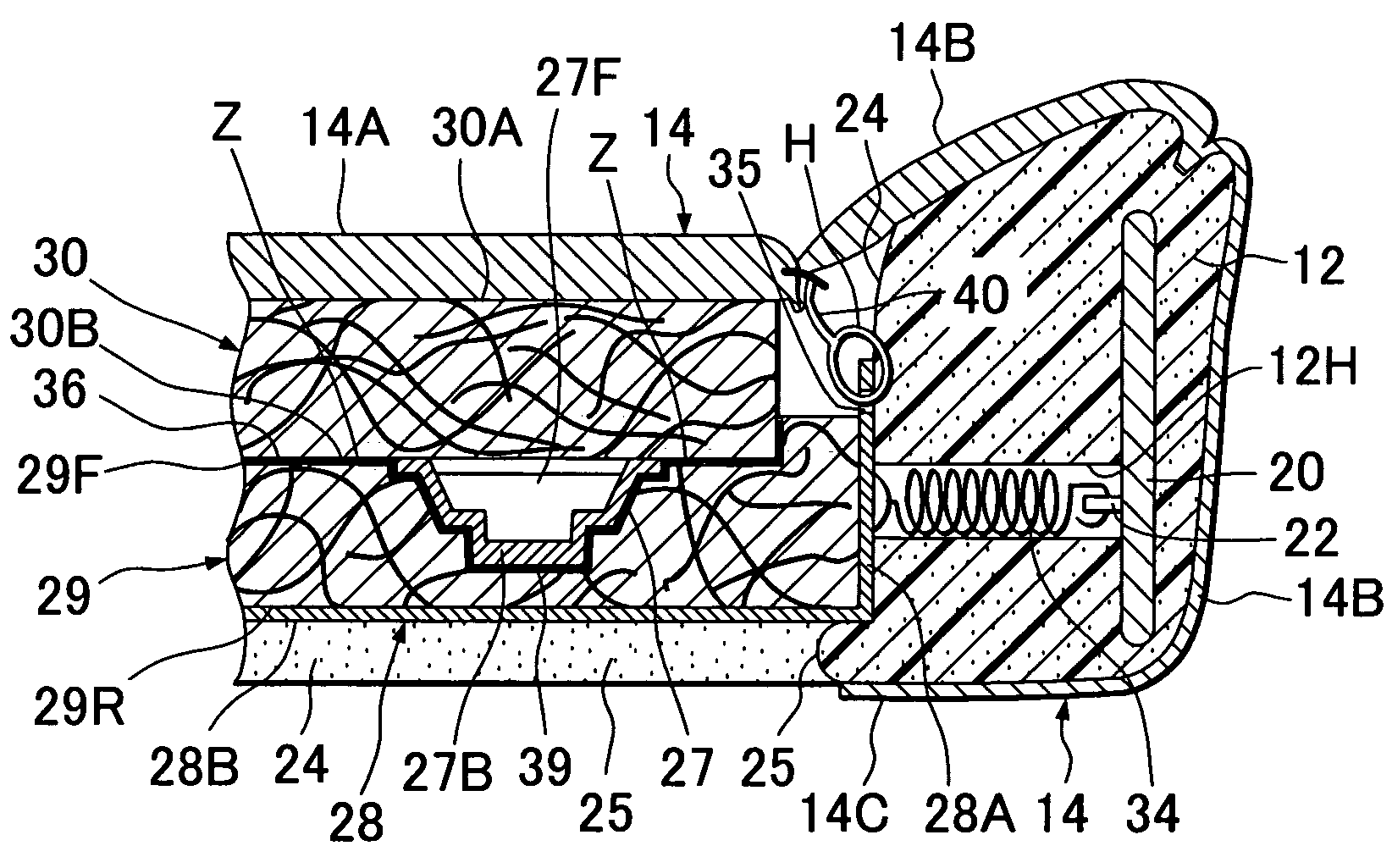
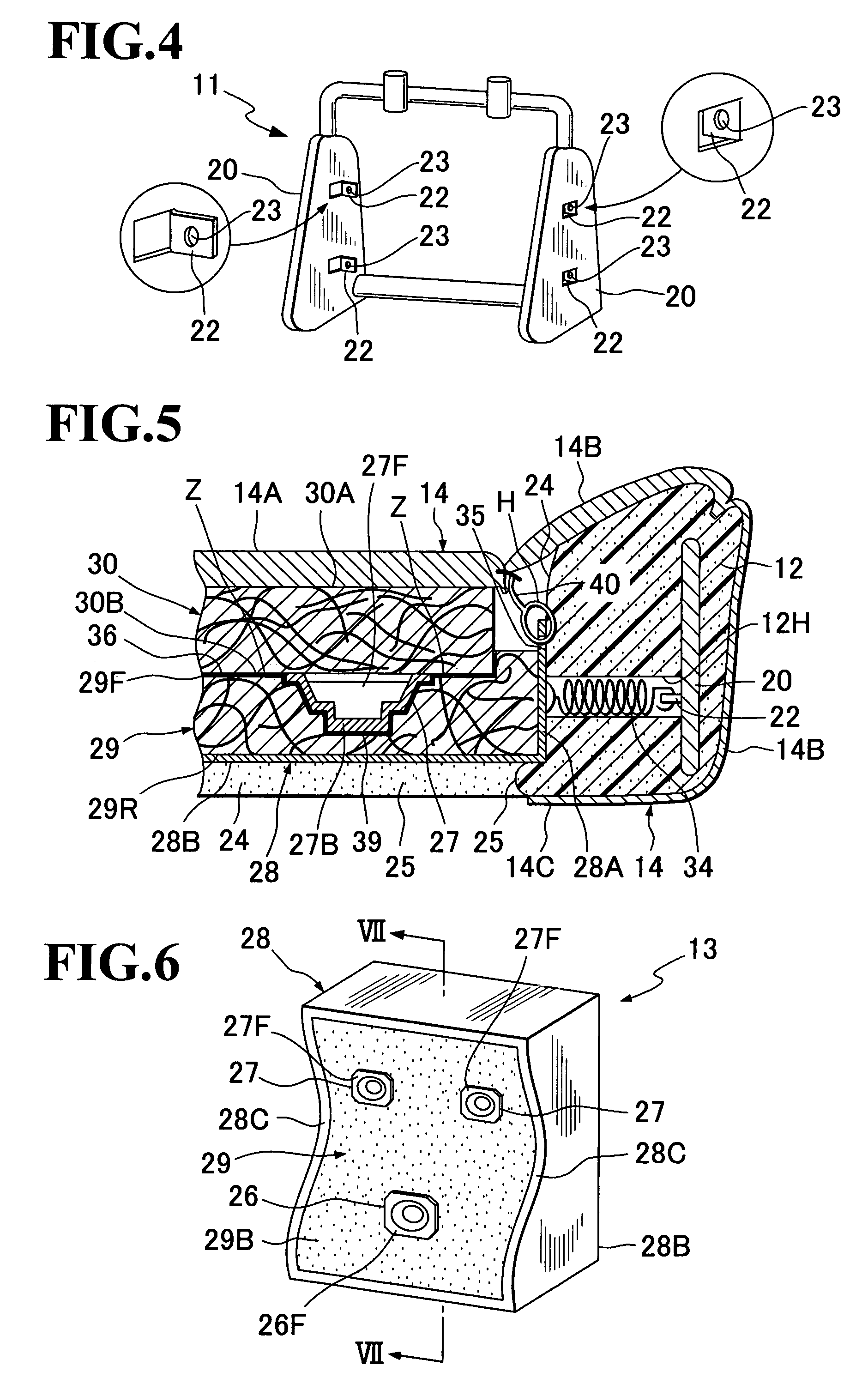
[0040]As generally shown in FIGS. 1 and 5, the acoustic structure (10) for the seat back (SB) (which shall hereinafter be referred to as “seat-back acoustic structure (10)”) is basically comprised of: an acoustic unit generally designated by (13); a seat-back foam padding (12) having a hole (24) in which the acoustic unit (13) is securely accommodated; and a trim cover assembly (14).

[0041]With particular reference to FIG. 2, the seat-back foam padding (12)...


PUM


Abstract

An acoustic structure of seat back, with an acoustic unit provided in a hole of padding of the seat back. The acoustic unit includes speaker unit(s) and a support box in which the speaker unit(s) is / are supportively received. The support box is accommodated in the afore-said hole of padding, with an opened side thereof facing to a forward side of the padding. A sound-conductive cushion element is supported by that support box so as to lie on a forward side of the speaker unit(s). The support box may include an acoustic hollow portion therein. Those padding and sound-conductive cushion element are covered with a trim cover assembly. A speaker support cushiony element may be provided in the support box to support the speaker unit(s), with a high sound conductivity. The speaker support cushiony element and / or the sound-conductive cushion element may be of network structure.

Description

BACKGROUND OF THE INVENTION[0001]1. Field of the Invention[0002]The present invention relates to a sound system in an automotive seat, and in particular to an acoustic structure of seat back provided with speakers, wherein a sound is emitted from speakers to an occupant or user on the seat.[0003]2. Description of Prior Arts[0004]There has been known an automotive seat of the type having speakers provided therein, which allows a sound, such as music, to be emitted from the speakers directly to an occupant on the seat, so that the occupant can fully enjoy the sound with both his or her ears and body.[0005]In this kind of seat, as disclosed from the Japanese Laid-Open Patent Publication No. 2002-346476, the speakers are provided behind a cushion material forming one constituent element of the seat so as to be in contact with a reverse side of the cushion material. While not taught in that literature, normally, the speakers are secured to a spring element typically provided in the seat....

Claims


Application Information

Patent Timeline
Patent Type & Authority Patents(United States)
IPC IPC(8): H04R1/02A47C31/00H04B1/00
CPCB60R11/0217B61D33/0007H04R1/025H04R5/023B60R2011/0015H04R2499/13
Inventor MATSUHASHI, MASAHIRO
Owner TACHI S CO LTD
Why Eureka
Try Eureka