Acoustic structure of seat back

a seat back and acoustic technology, applied in the field of sound systems, can solve the problems of not being able to enjoy music satisfactorily, not being able to impart sound through, and avoiding conventional etc., to achieve the effect of improving the acoustic structure of seats, high air permeability, and high cushioning

Inactive Publication Date: 2007-01-09
TACHI S CO LTD
View PDF11 Cites 69 Cited by
  • Summary
  • Abstract
  • Description
  • Claims
  • Application Information

AI Technical Summary

Benefits of technology

[0010]In view of the above-stated drawbacks, it is a purpose of the present invention to provide an improved acoustic structure of seat back which allows for wide expansion of a sound emitted from speakers in seat back to an entire area of back of a seat occupant, thereby giving the occupant a splendid impression as if the music was actually and vividly played, while allowing for provision of a high cushiony effect and a high air permeability.

Problems solved by technology

The foregoing conventional acoustic structure of seat has, however, been found defective in that:
(i) the cushion material used is a foam padding material formed from urethane foam for optimal cushioning effect, but, is not suited for imparting the sound therethrough because of its property of absorbing sound and degrading acoustic effect, and
(ii) the sound emitted from each speaker is limited to a region which is substantially compassed by a diameter of the speaker itself, and such limited range of sound emission is directed to the back of an occupant on the seat, as a result of which, the occupant can not enjoy the music satisfactorily, and can not feel such vivid sound as if the music was performed in a real concert hall, neither, due to the foregoing sound absorption by the foam cushion material.
However, such exposed speakers interfere with the occupant's movement, thus impairing a comfortable seating condition of the seat, and further, the range of sound emission from such exposed speaker arrangement is limited to a narrow space around the seat occupant, so that the occupant can not fully enjoy the sound or music with his or her body.

Method used


Image

  • Acoustic structure of seat back
  • Acoustic structure of seat back
  • Acoustic structure of seat back

Examples


second embodiment

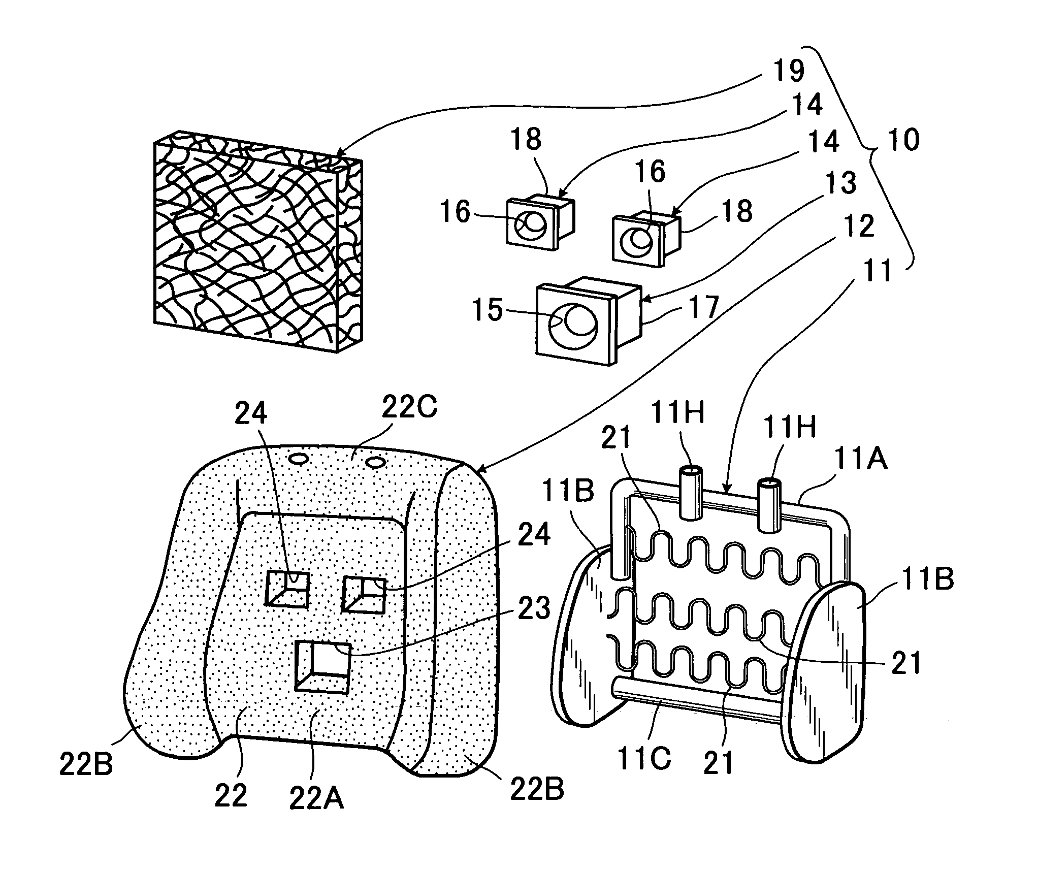
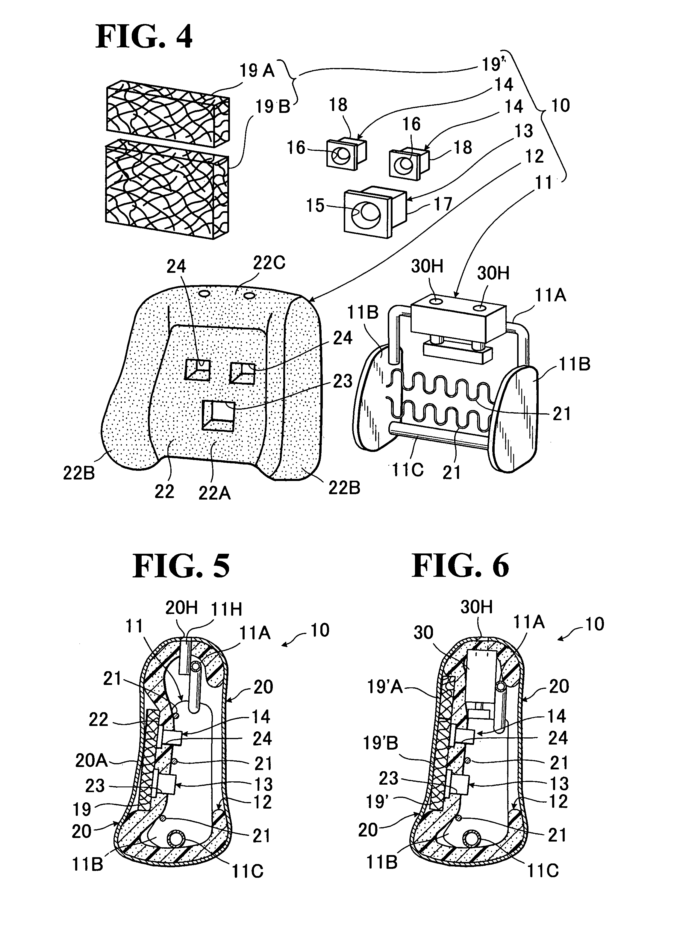
[0045]FIGS. 4 and 6 show a second mode of acoustic structure (10) which is suggested in connection with the effect given at the item (iv) above. This particular second embodiment is basically identical in structure to the above-described firsts mode, except that a second mode of sound-conductive cushiony plate element (19) is provided, which comprises a pair of first and second sound-conductive cushiony plate elements (19A) (19B) and that a known active headrest support mechanism (30) is mounted on the upper frame section (11A) of seat back frame (11), the active headrest support mechanism (30) being operable to cause vertical movement of a headrest (not shown). Hence, all like designations to be used hereinafter correspond to all like designations given in the foregoing first mode, and any specific description is omitted on common elements and parts between the first and second modes for the sake of simplicity.

[0046]As shown in FIG. 4, the sound-conductive cushiony plate element (1...

first embodiment

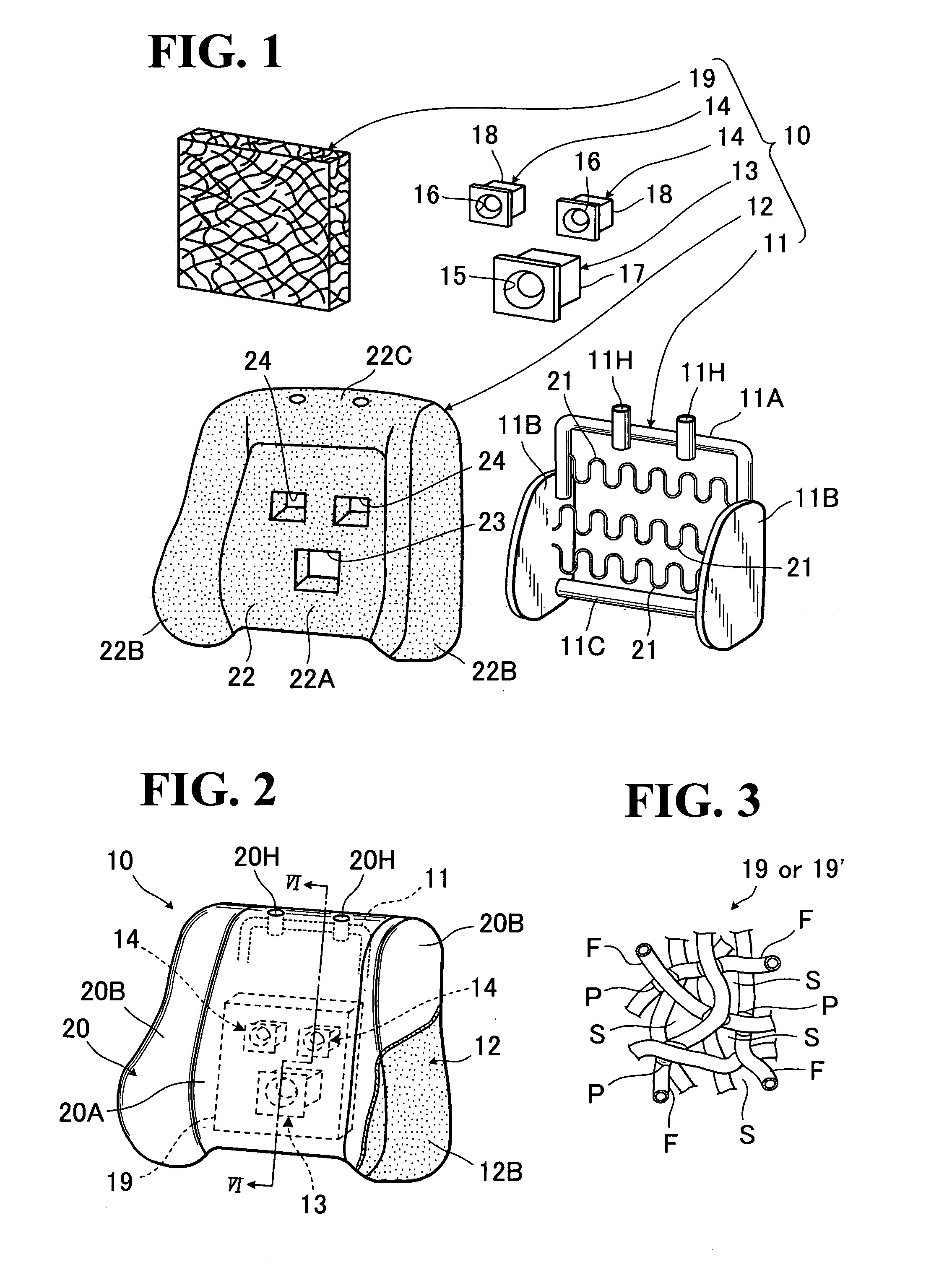
[0048]Likewise in the first embodiment, both two network cushiony plate members (19A) (19B) are formed from the straw-like fiber (F) bent and tangled, with a plurality points thereof are adhered to one another by means of thermal fusing, as indicated by (P), with spaces (S) given among the thus-tangled and adhered fiber (F), so as to form a network cushiony plate member having a high sound conductivity. Also, a whole of the two network cushiony plate members (19A) (19B) has a depth generally equal to the afore-stated backwardly recessed degree of the central portion (22A), and, in other words, a whole of those two members (19A) (19B) are generally equal in dimensions to the recessed central frontal backrest surface area (22A) of foam padding (22).

[0049]As shown in FIG. 6, the first and second network cushiony plate members (19A) (19B) are juxtaposed on and secured to a whole area of the central portion (22A) of foam padding (22) so as to overlie all the speaker units (14) (18). In t...


PUM


Abstract

An acoustic structure of seat back in which speaker units are provided in a padding of the seat back. The padding includes: a frontal backrest surface area which is recessed backwardly of the seat back; and securing holes formed in that frontal backrest surface area. An enclosure of each speaker unit, in which each speaker is securely accommodated, is secured in each of the securing holes. A sound-conductive cushion element is juxtaposed on the foregoing recessed frontal backrest surface area of padding so as to lie on a frontal side of each of the speaker units. The sound-conductive cushion element may be of a network structure to not only provide an improved back support touch, but also achieve an improved conductivity of sounds from the speaker units to a user's back portion. Those padding and sound-conductive cushion element are covered with a trim cover assembly.

Description

BACKGROUND OF THE INVENTION[0001]1. Field of the Invention[0002]The present invention relates to a sound system in an automotive seat, and in particular to an acoustic structure of seat back provided with speakers, wherein a sound is emitted from speakers to an occupant on the seat.[0003]2. Description of Prior Arts[0004]There has been known an automotive seat of the type having speakers provided therein, which allows a sound, such as music, to be emitted from the speakers directly to an occupant on the seat, so that the occupant can fully enjoy the sound with both his or her ears and body.[0005]In this kind of seat, as disclosed from the Japanese Laid-Open Patent Publication No. 2002-346476, the speakers are provided behind a cushion material forming one constituent element of the seat so as to be in contact with a reverse side of the cushion material. While not taught in that literature, normally, the speakers are secured to a spring element typically provided in the seat.[0006]Th...

Claims


Application Information

Patent Timeline
Patent Type & Authority Patents(United States)
IPC IPC(8): A47C7/62
CPCB60N2/70B60R11/0217H04R1/025B60R2011/0015H04R2499/13H04R1/26H04R5/023
Inventor SHIRAISHI, MITSURU
Owner TACHI S CO LTD
Why Eureka
Try Eureka