Frequency synthesizer, coupled divide-by-N circuit, current-reuse multiply-by-M circuit

a frequency synthesizer and multiply-by-m technology, applied in the field of frequency synthesizers, can solve problems such as occupying more circuit area, and achieve the effect of reducing the generated mismatch

Inactive Publication Date: 2010-03-02
NAT TAIWAN UNIV
View PDF5 Cites 23 Cited by
  • Summary
  • Abstract
  • Description
  • Claims
  • Application Information

AI Technical Summary

Benefits of technology

[0010]Preferably, a plurality of inverters are connected to each of the pair of divide-by-N circuits so as to reduce a mismatch generated therefrom.

Problems solved by technology

Nevertheless, since these two circuits are usually operated with a higher workable frequency that consumes massive power and the multiply-by-3 circuit includes the passive component, these two circuits occupy more circuit area.

Method used


Image

  • Frequency synthesizer, coupled divide-by-N circuit, current-reuse multiply-by-M circuit
  • Frequency synthesizer, coupled divide-by-N circuit, current-reuse multiply-by-M circuit
  • Frequency synthesizer, coupled divide-by-N circuit, current-reuse multiply-by-M circuit

Examples


Embodiment Construction

[0052]The present invention will now be described more specifically with reference to the following embodiments. It is to be noted that the following descriptions of preferred embodiments of this invention are presented herein for the aspect of illustration and description only; it is not intended to be exhaustive or to be limited to the precise from disclosed.

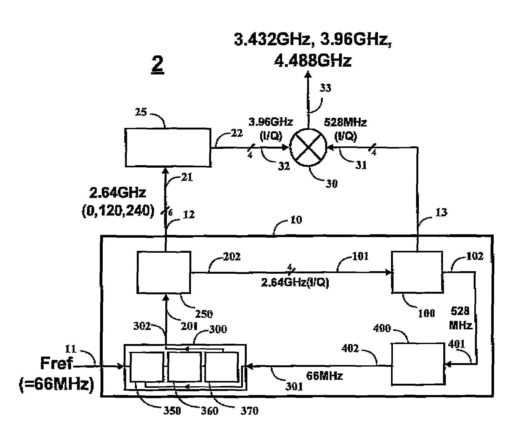
[0053]Please refer to FIG. 6 which is a diagram illustrating a first preferred embodiment of the frequency synthesizer according to the present invention. The frequency synthesizer architecture 2 in accordance with the first preferred embodiment of the present invention which includes a single phase-locked loop 10 having a reference frequency signal input 11, a first output 12, a second output 13 and a pair of divide-by-5 circuits coupled with each other included in the single phase-locked loop 10 which circuits are a plurality of coupled divide-by-5 circuit and electrically connected to the second output 13. A multiply-by-1.5...


PUM


Abstract

A frequency synthesizer is provided in the present invention. The frequency synthesizer includes a single phase-locked loop having a reference frequency signal input, a first output, a second output and a pair of divide-by-N circuits coupled with each other and electrically connected to the second output; a multiply-by-M circuit having a first input electrically connected to the first output and a third output; and a combination of a buffer and a mixer having a second input electrically connected to the second output and a third input electrically connected to the third output generating a frequency signal output.

Description

FIELD OF THE INVENTION[0001]The present invention relates to a frequency synthesizer, in particular, to a frequency synthesizer of the multiply-by-1.5 circuit.BACKGROUND OF THE INVENTION[0002]Please refer to FIG. 1, which is a diagram illustrating a frequency synthesizer according to the prior art. The frequency synthesizer is a kind of component used for providing various kinds of frequencies in one or many reference frequency circuits. Usually, in the frequency synthesizer, the multiply phase locked loop would be adopted therein in order to obtain a series of frequency signals. Take it as the example the frequency synthesizer architecture 1 illustrating in FIG. 1, where a phase locked loop 80 receives a reference frequency 81; a UP and DN signal are outputted by a phase frequency detector 91 in the phase locked loop 80; a digital comparison signal is transformed into an analogy current signal by a charge pump 92; a control voltage Vctrl is then obtained by filtering the analogy cu...

Claims


Application Information

Patent Timeline
Patent Type & Authority Patents(United States)
IPC IPC(8): H03B21/00
CPCG06F7/68H03K23/48H03L7/183
Inventor FAN, CHE-WEILIU, SHEN-IUAN
Owner NAT TAIWAN UNIV
Why Eureka
Try Eureka