Computerized method for adherence to physical restriction in the construction of an ITE hearing aid

a technology of hearing aids and computerized methods, applied in the field of computerized methods for hearing aid construction in the ear, can solve the problems of unoptimized use of the auditory canal space, and achieve the effect of improving the ability to position components

Active Publication Date: 2010-03-02
SIEMENS AG
View PDF4 Cites 10 Cited by
  • Summary
  • Abstract
  • Description
  • Claims
  • Application Information

AI Technical Summary

Benefits of technology

[0012]An object of the present invention is to provide a computerized method that improves the ability to position components in an ITE hearing aid, with adherence to physical restrictions.

Problems solved by technology

Moreover, depending on the individual anatomy of the auditory canal, the available space in the auditory canal often is not optimally utilized.

Method used


Image

  • Computerized method for adherence to physical restriction in the construction of an ITE hearing aid
  • Computerized method for adherence to physical restriction in the construction of an ITE hearing aid
  • Computerized method for adherence to physical restriction in the construction of an ITE hearing aid

Examples


Embodiment Construction

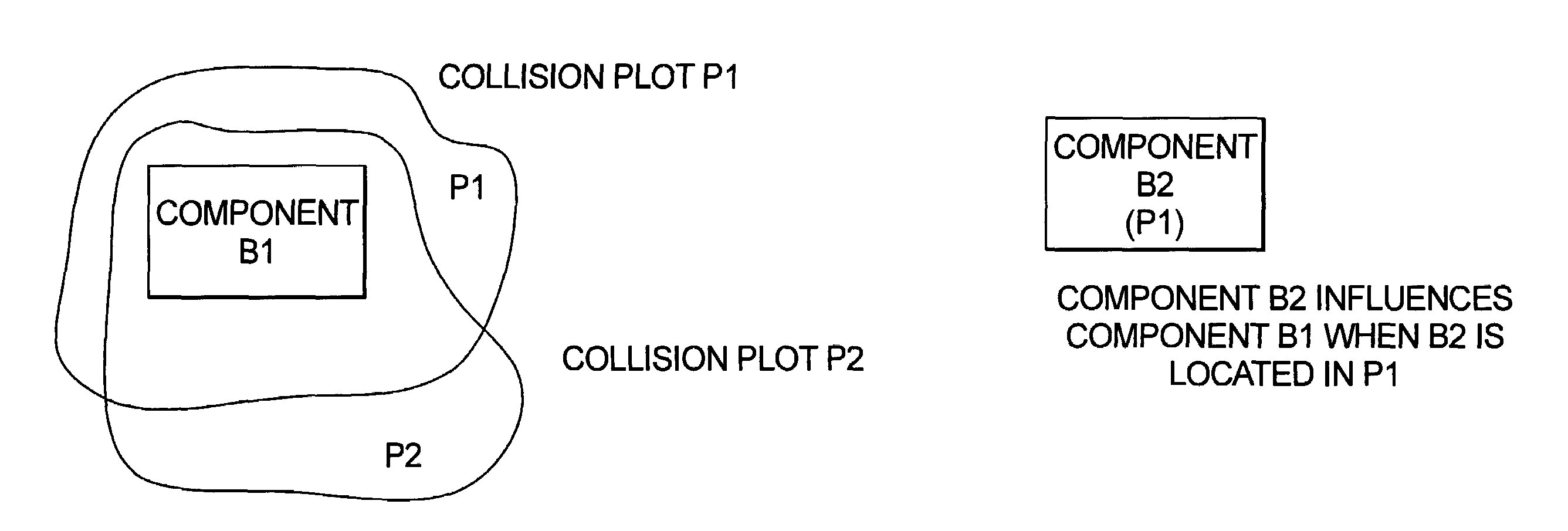
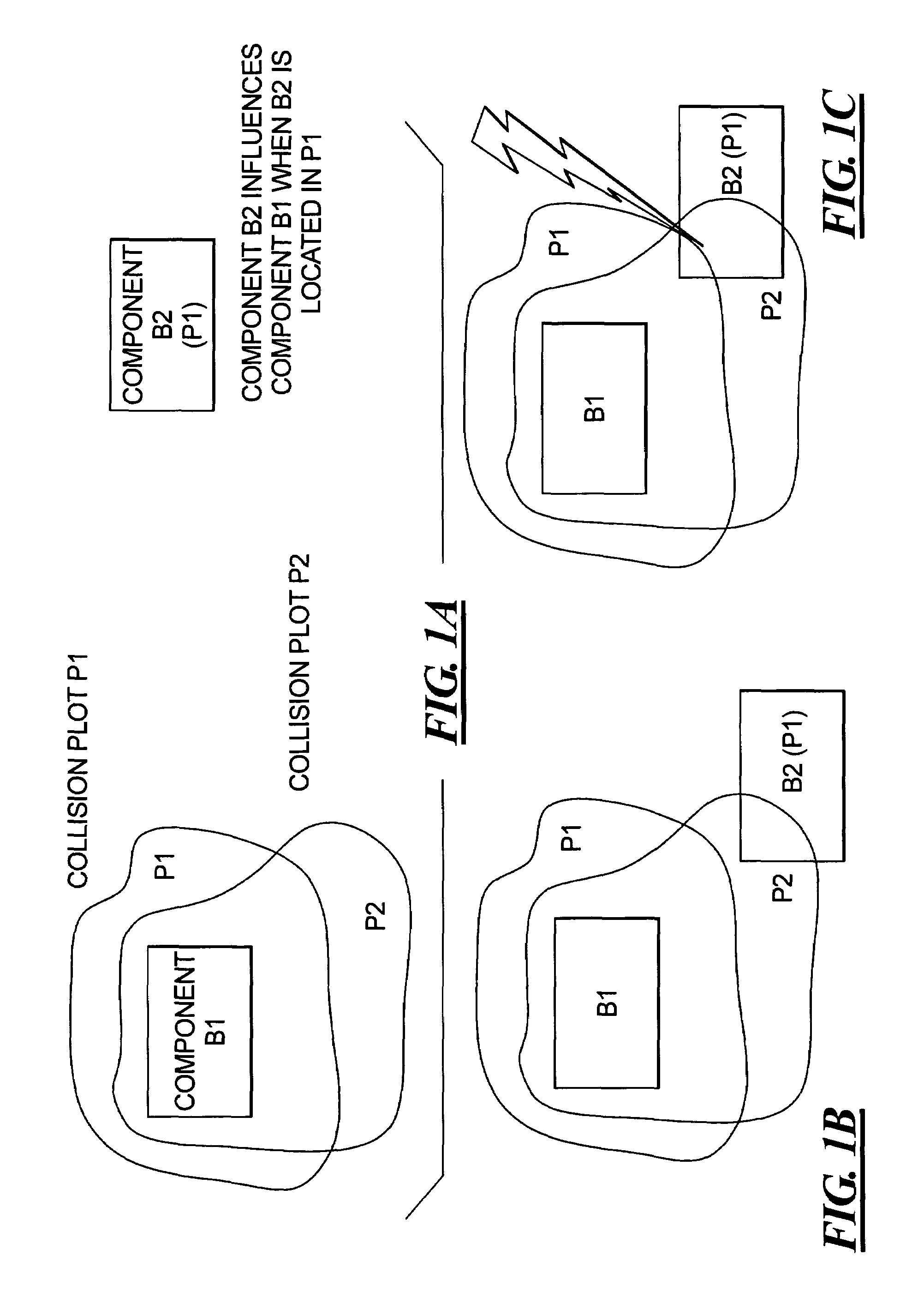
[0018]FIG. 1A schematically illustrates the concept of the use of collision plots in the e-detailing software for constructing an ITE hearing aid. Component B1 has a collision plot P1 logically linked thereto, and component B2 has a collision plot P2 logically linked thereto. The respective collision plots are scatter plots that are determined by suitable measurements, simulations, etc., and are represented in a suitable file format, such as STL. In the e-detailing software, the collision plots are respectively linked to the components associated therewith, so that as the virtual representations of the components are moved or adjusted in the e-detailing software, the collision plot that is logically linked thereto moves correspondingly. As indicated in FIG. 1A, component B2 influences component B1 when B2 is located in collision plot P1.

[0019]FIG. 1B illustrates an acceptable situation for the component B2 with respect to the collision plot P1 of the component B1, because the virtua...


PUM


Abstract

In a computerized method for adherence to physical restrictions in the construction of an ITE hearing aid, each component to be placed in the shell of the hearing aid has a collision plot associated therewith. The collision plot is generated as a scatter plot by measurement and simulation, and represents the physical extent of the influence of a particular property of the component on other components. When virtual representations of the respective components are moved relative to another in the e-detailing software for determining the physical positions of the components in the ITE hearing aid, the collision plot for a given component is visually displayed, so that it can easily be seen when another component invades that collision plot, thereby representing an unacceptably close relative position of the two components.

Description

BACKGROUND OF THE INVENTION[0001]1. Field of the Invention[0002]The present invention concerns a computerized method for use in the construction of an ITE (in the ear) hearing aid, and in particular to such a computerized method that causes the internal components within an ITE hearing aid to be positioned at appropriate locations.[0003]2. Description of the Prior Art[0004]An ITE hearing aid is a customized device that must conform to the individual anatomy of the hearing impaired person who will wear the ITE hearing aid. An ITE hearing aid generally is formed by a shell (also called an otoplastic) that is produced from a mold that has been made of the auditory canal of the person who will wear the ITE hearing aid. The interior of the shell is hollow, but has a shape that is dictated by the customized exterior shape of the shell. The shell generally tapers toward a narrow-most end, which will be fitted into the interior of the auditory canal, and at which the sound exit opening is l...

Claims


Application Information

Patent Timeline
Patent Type & Authority Patents(United States)
IPC IPC(8): G06F17/50G06G7/48H04R25/00H04R29/00
CPCH04R25/652H04R2225/77H04R2225/025
Inventor NIKLES, PETERMARTINEWSKI, ERIKAGEBHARDT, VOLKERISMAIL, BASSEMBOLTYENKOV, ARTEMMCBAGONLURI, FRANK
Owner SIEMENS AG
Why Eureka
Try Eureka