Tendon tensioning anchor system having polymeric encapsulation with reduced shrinkage effects

a technology of polymeric encapsulation and tensile anchors, which is applied in the direction of building components, building reinforcements, constructions, etc., can solve the problems of insufficient use of concrete full potentialities, weak carrying of significant tensile loads, and inability to carry structural concrete load

Active Publication Date: 2010-03-16
SORKIN FELIX L
View PDF12 Cites 39 Cited by
  • Summary
  • Abstract
  • Description
  • Claims
  • Application Information

AI Technical Summary

Problems solved by technology

On the other hand, structural concrete, though quite capable of carrying almost any compressive (vertical) load, is extremely weak in carrying significant tensile loads.
Structures of reinforced concrete may be constructed with load-bearing walls, but this method does not use the full potentialities of the concrete.
Metallic components within concrete structures may become exposed to many corrosive elements, such as de-icing chemicals, sea water, brackish water, or spray from these sources, as well as salt water.
If this occurs, and the exposed portions of the anchor suffer corrosion, then the anchor may become weakened due to this corrosion.
The deterioration of the anchor can cause the tendons to slip, thereby losing the compressive effects on the structure, or the anchor can fracture.
In addition, the large volume of byproducts from the corrosive reaction is often sufficient to fracture the surrounding structure.
These elements and problems can be sufficient so as to cause a premature failure of the post-tensioning system and a deterioration of the structure.
When the polymeric encapsulation tends to pull away from surfaces 48 and 50, several problems can result.

Method used


Image

  • Tendon tensioning anchor system having polymeric encapsulation with reduced shrinkage effects
  • Tendon tensioning anchor system having polymeric encapsulation with reduced shrinkage effects
  • Tendon tensioning anchor system having polymeric encapsulation with reduced shrinkage effects

Examples


Embodiment Construction

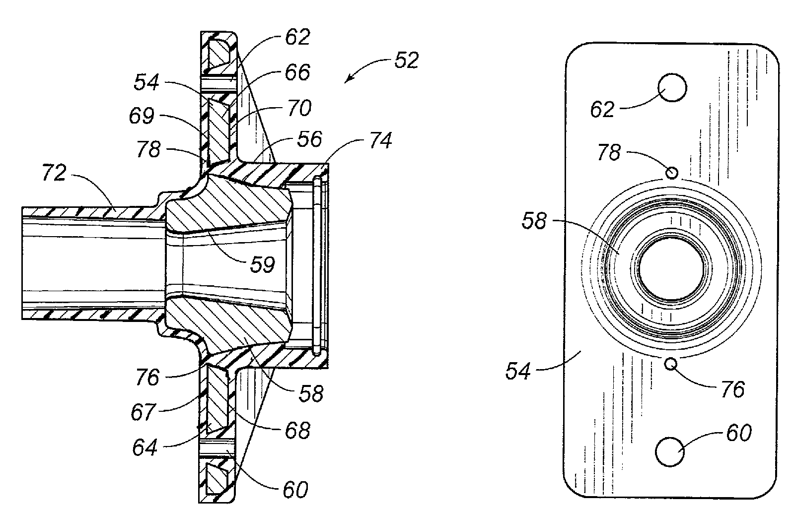
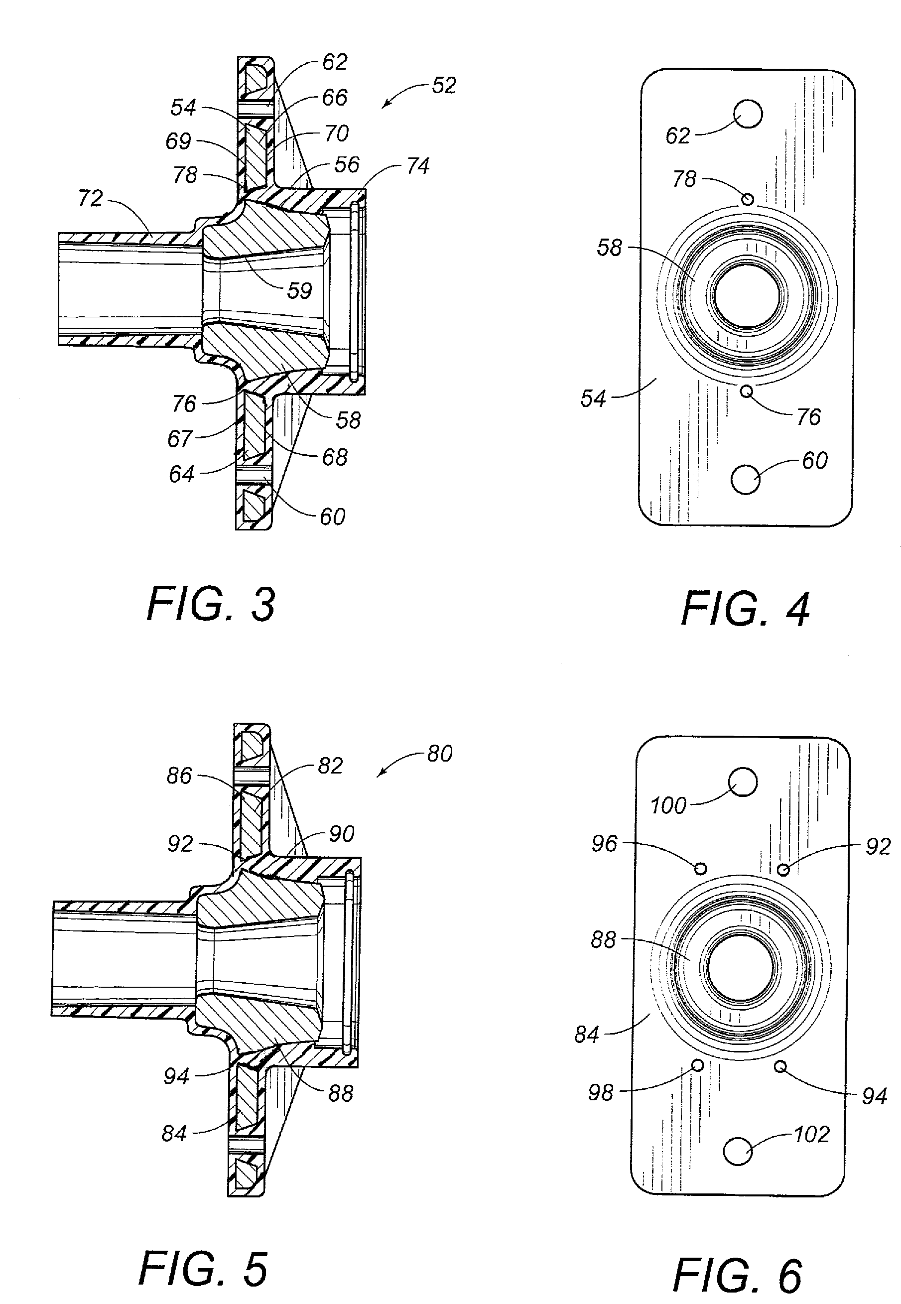
[0035]Referring to FIG. 3, there is shown the tendon tensioning anchor 52 in accordance with the preferred embodiment of the present invention. The tendon tensioning anchor 52 includes a base member 54 having a polymeric encapsulation 56 extending thereover and therearound. In particular, the base member 54 is a steel construction anchor having a tubular section 58 extending outwardly centrally thereof. The tubular section 58 has a sloping annular interior wall 59 suitable for receiving a tendon therein. The anchor 54 includes nail holes 60 and 62 formed through the respective flanges 64 and 66. Flanges 64 and 66 extend outwardly on opposite sides of the tubular section 58. Flange 64 has a first surface 67 and a second surface 68. The flange 66 has a first surface 69 and a second surface 70.

[0036]The polymeric encapsulation 56 will extend over and around the tubular section 58 and over and around the flanges 64 and 66. The polymeric encapsulation will also define a tubular portion 7...


PUM


Abstract

A tendon tensioning anchor has a base member having a tubular section extending therefrom, and a pair of flanges extending outwardly on opposite sides of the tubular section, and a polymeric encapsulation in generally air-tight juxtaposition with an exterior of the base member. A hole is formed through each of the pair of flanges. The polymeric encapsulation extends entirely through and fills the holes so as to integrally connect the polymeric material overlying one surface of the flange with the polymeric material overlying an opposite surface of the flange. The hole is formed adjacent to the tubular section.

Description

RELATED U.S. APPLICATIONS[0001]Not applicable.STATEMENT REGARDING FEDERALLY SPONSORED RESEARCH OR DEVELOPMENT[0002]Not applicable.REFERENCE TO MICROFICHE APPENDIX[0003]Not applicable.FIELD OF THE INVENTION[0004]The present invention relates to tendon tensioning anchors. More particularly, the present invention relates to tendon tensioning anchors that have a polymeric encapsulation extending thereover so as to seal exterior surfaces of the anchor from the environment.BACKGROUND OF THE INVENTION[0005]For many years, the design of concrete structures imitated the typical steel design of column, girder and beam. With technological advances in structural concrete, however, its own form began to evolve. Concrete has the advantages of lower cost than steel, of not requiring fireproofing, and of its plasticity, a quality that lends itself to free flowing or boldly massive architectural concepts. On the other hand, structural concrete, though quite capable of carrying almost any compressive...

Claims


Application Information

Patent Timeline
Patent Type & Authority Patents(United States)
IPC IPC(8): E04C5/08E04C5/12
CPCE04C5/12
Inventor SORKIN, FELIX L.
Owner SORKIN FELIX L
Why Eureka
Try Eureka