Lift magnet mechanism for flywheel power storage systems
What is AI technical title?
AI technical title is built by Patsnap AI team. It summarizes the technical point description of the patent document.
a technology of power storage system and magnet mechanism, which is applied in the direction of propulsion system, mechanical energy handling, mechanical apparatus, etc., can solve the problems of storage space, material restrictions, other factors inherent in the nature of materials, and magnetic arrays, so as to relieve mechanical bearing wear, reduce power loss, and reduce the effect of eddy current loss
Inactive Publication Date: 2010-03-16
BEACON POWER LLC
View PDF17 Cites 19 Cited by
Summary
Abstract
Description
Claims
Application Information
AI Technical Summary
This helps you quickly interpret patents by identifying the three key elements:
Problems solved by technology
Method used
Benefits of technology
Benefits of technology
[0012]The salient objectives of the instant invention center around improvement of high capacity, flywheel energy storage systems and particularly around improvement upon inherent bearing wear, control of magnetic flux and minimization of required lift power fluctuation. Thus, creation of a system, subsystem, mechanism or method of operation which minimizes the load on the ball bearings, in the case where the high speed rotor should release and begin to plummet down on the ball bearings during potential failure mode, is crucial.
[0021]Thus, one specific objective of the instant invention is to provide a system that eradicates the power spikes generated by prior systems due to physical spacing consideration inherent in applications possessing large circular pieced together magnet members.
Problems solved by technology
As also illustrated in the above-referenced United States patents, such means as rechargeable electrochemical batteries offer some usages, but encounter huge problems involving key issues such as storage space, leakage and longevity.
However, as flywheel power storage system designs have evolved from smaller, physically limited structures with minimal storage capacity to the high capacity systems employing industrial sized magnetic members prevalent today, material restrictions and other such factors inherent with have arisen.
In modern applications, due to the need for extremely large magnetic arrays and magnetic members, current manufacturing capabilities restrict magnetic arrays to structures containing joined magnetic segments.
High sensitivity implies low magnetic force as the gap is large and excessively high force as the gap is small.
Lower force at the large gap requires designs with either stronger magnets or higher current to lift the rotor, and excessively high force at small gap would potentially damage the parts under the fault conditions.
Previous failure of high capacity flywheel systems often is found to be triggered by overloading and overheating of the touchdown ball bearing.
When utilizing a pure electromagnet lift magnet, failure offer occurs as the electrical power is tripped during normal operation due to the high lifting force requirement.
As the lifting force dissipates, the heavy rotor will then sit on the ball bearings, and thus, due to the heavy load, will heat up the ball bearings in a short expense of time.
Thus, as the ball bearing fails, the high speed rotor loses the mechanical support, and rotates basically out of round, contacting the casing.
Thus, wear, catastrophic at times and even explosions within the casing may occur.
High sensitivity implies that low magnetic force occurs when the gap is large in magnitude and excessively high force occurs when the gap is small in magnitude.
The larger gap condition at which lower force occurs requires designs with either stronger magnets or higher current to lift the rotor; whereas, on the other hand, the excessively high force at small gap could potentially damage parts or the overall system under fault conditions.
Method used
Image
Click on the blue label to locate the original text in one second.
Reading with bidirectional positioning of images and text.
Examples
Embodiment Construction
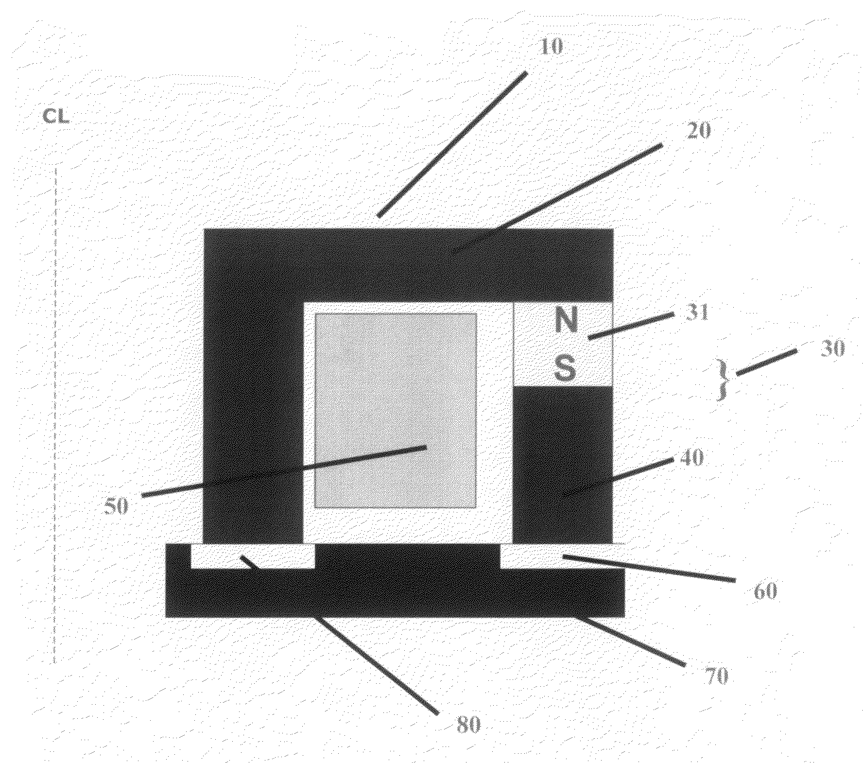
[0037]In flywheel driven power storage systems, the magnetic force generated either by permanent magnet or electromagnet or the combination of both is used to lift the rotor in a flywheel system. The magnetic force generated by a pair of stationary stator and rotor is normally highly sensitive to the air gap separating the stator and rotor. High sensitivity implies low magnetic force, as the gap is large and excessively high force as the gap is small.
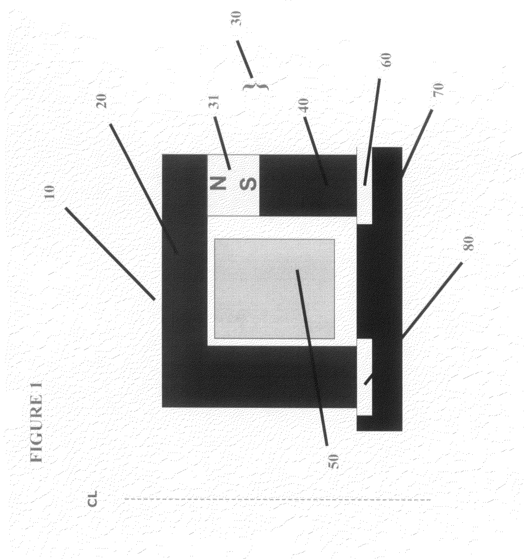
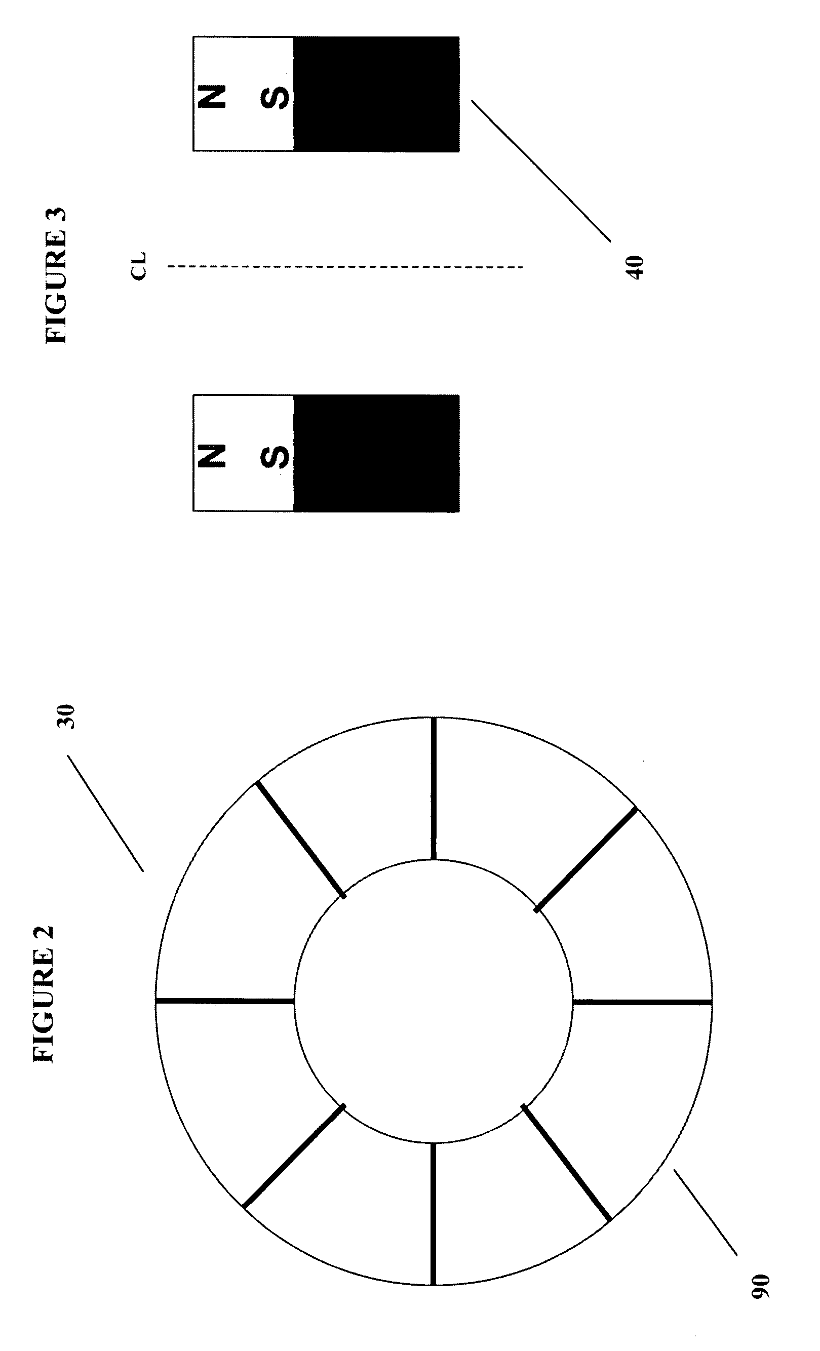
[0038]In order illustrate the numerous embodiments of the instant invention, referring first to FIG. 1 illustrates a simplified cutaway assembly block diagram of the flywheel power storage system magnetic ring apparatus 10 or magnetic lift portion of the instant flywheel battery, illustrating the stator housing and assembly 20, the permanent magnet array 30 which is comprised of segmented magnet array 31 and the steel cylindrical member 40 or pole 40, the coil 50, the gap between rotor and stator, or rotor / stator gap 60, and the rotor 7...
PUM
Abstract
Electric power is stored in a flywheel assembly, from a dc power buss, and supplied to the buss, through electronics associated with a motor / generator, its rotor integral with a flywheel supported by magnetic bearings. Upon operation, the flywheel assembly is released by mechanical backup bearings which then normally remain disengaged until shutdown as the flywheel assembly is levitated by the axial magnetic field. Enhancements developed herein smooth the flux density across discontinuities or segments present in permanent magnets due to presently limited capability for manufacture of large annular magnetic members. Herein, the introduction of a medium such as a steel cylindrical member to directly interface with the rotor as opposed to the segmented permanent magnet, greatly eradicates induced eddy current and heat on the rotor. In addition, exhibited is an annularly slotted rotor which allows for greater surface area for flux absorption.
Description
FIELD OF THE INVENTION[0001]The present invention relates generally to flywheel driven power storage systems and particularly to enhancements developed to smooth the flux density across discontinuities or segments present in permanent magnets due to present manufacturing capability.REFERENCES[0002]In general within the art, descriptions of flywheel driven power storage systems and their various related elements can be found in U.S. Pat. Nos. 5,614,777 set forth by Bitterly et al; 5,767,595, 5,708,312, 5,770,909, and 5,864,303 by Rosen et al; 3,860,300 and 4,147,396 by Lyman; 3,791,704 and 4,088,379 by Perper; 5,627,419 by Miller; 4,910,449 by Hiyama et al: 5,760,510 by Nomura et al: 5,777,414 by Conrad; 5,319,844 by Huang et al; 4,444,444 by Benedetti et al; 5,844,339 by Schroeder et al; 5,495,221, 5,783,885, 5,847,480, 5,861,690, and 5,883,499 by Post; 5,705,902 by Merritt et al; 5,044,944 and 5,311,092 by Fisher; 5,107,151 and 5,677,605 by Cambier et al; and 5,670,838 by Everton; ...
Claims
Application Information
Patent Timeline
Application Date:The date an application was filed.
Publication Date:The date a patent or application was officially published.
First Publication Date:The earliest publication date of a patent with the same application number.
Issue Date:Publication date of the patent grant document.
PCT Entry Date:The Entry date of PCT National Phase.
Estimated Expiry Date:The statutory expiry date of a patent right according to the Patent Law, and it is the longest term of protection that the patent right can achieve without the termination of the patent right due to other reasons(Term extension factor has been taken into account ).
Invalid Date:Actual expiry date is based on effective date or publication date of legal transaction data of invalid patent.

