
Roller bearing

a roller bearing and roller bearing technology, applied in the field of roller bearings, can solve the problems that the roller bearing is not equipped to compensate, and achieve the effect of increasing stiffness and increasing pre-tension

Inactive Publication Date: 2010-03-23
ZF LENKSYSTEME GMBH
View PDF29 Cites 7 Cited by
  • Summary
  • Abstract
  • Description
  • Claims
  • Application Information

AI Technical Summary

Benefits of technology

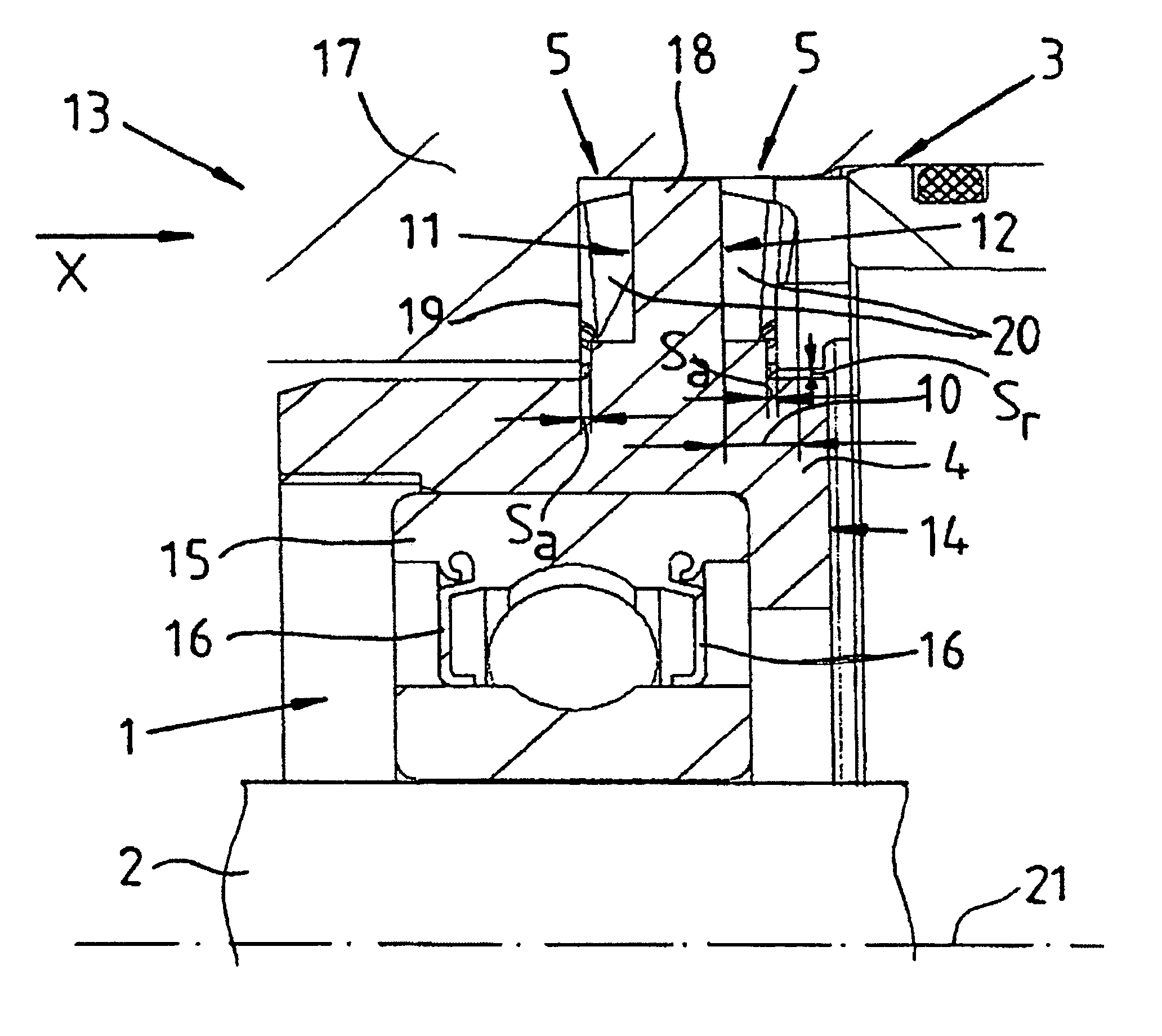
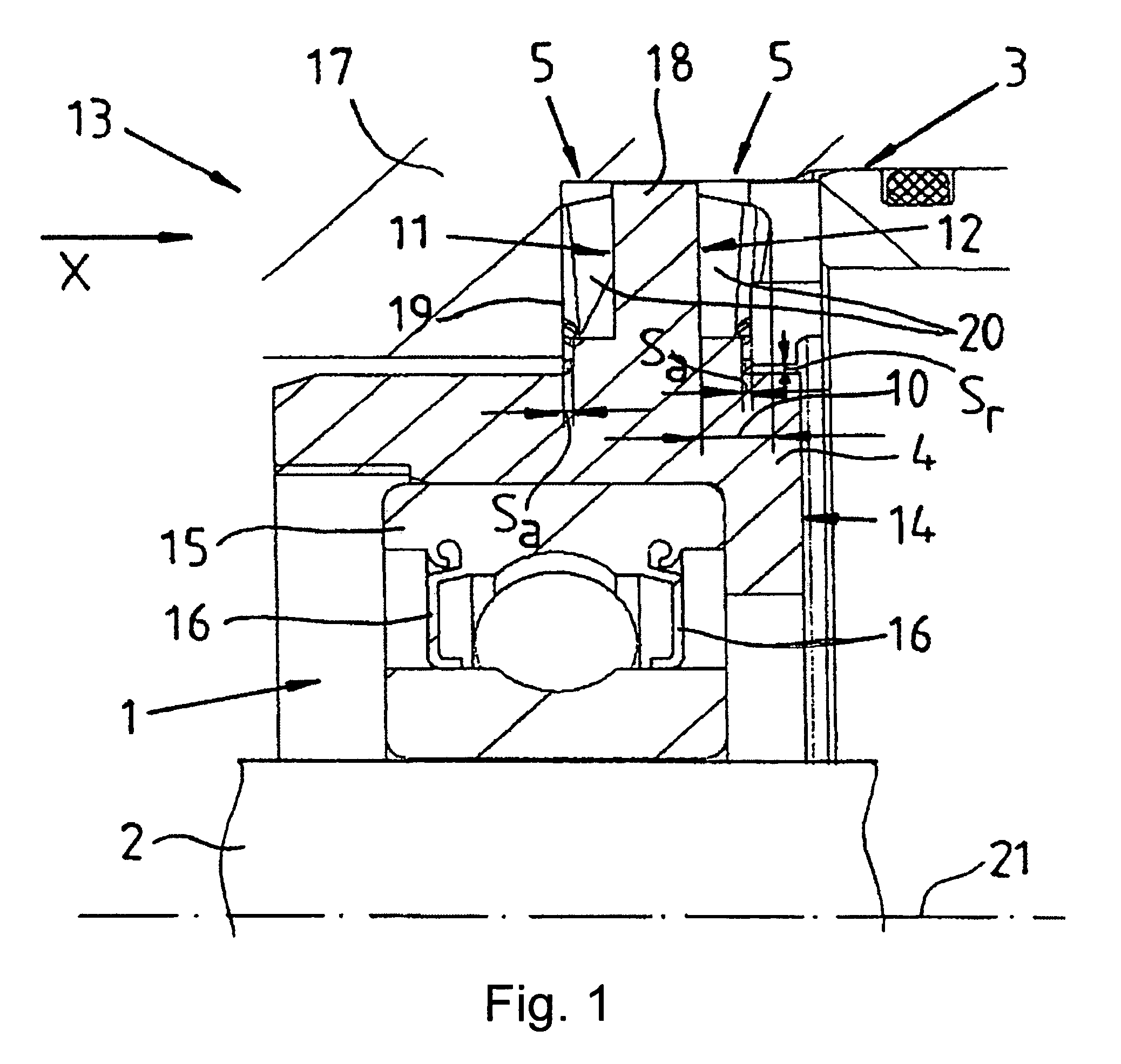
[0008]By virtue of the fact that the element with elastomeric properties, when considered in the tangential or circumferential direction of the roller bearing, has at least a first region, which has a stiffness different from that of the remaining tangential region, an axially and radially effective supporting element with elastomeric properties is provided for supporting the roller bearing at the rack. Due to its region of increased stiffness, the supporting element defines a center of gravity, about which the roller bearing and the shaft can swivel in a defined, limited, manner when subjected to a bending moment and straining of the system of shaft, roller bearing and rack is avoided. At the same time, a very slight axial clearance of the shaft is retained. Moreover, due to the geometric assignment of the region of increased stiffness, a preferential pivoting direction to the roller bearing and the shaft can be defined at the element with elastomeric properties.
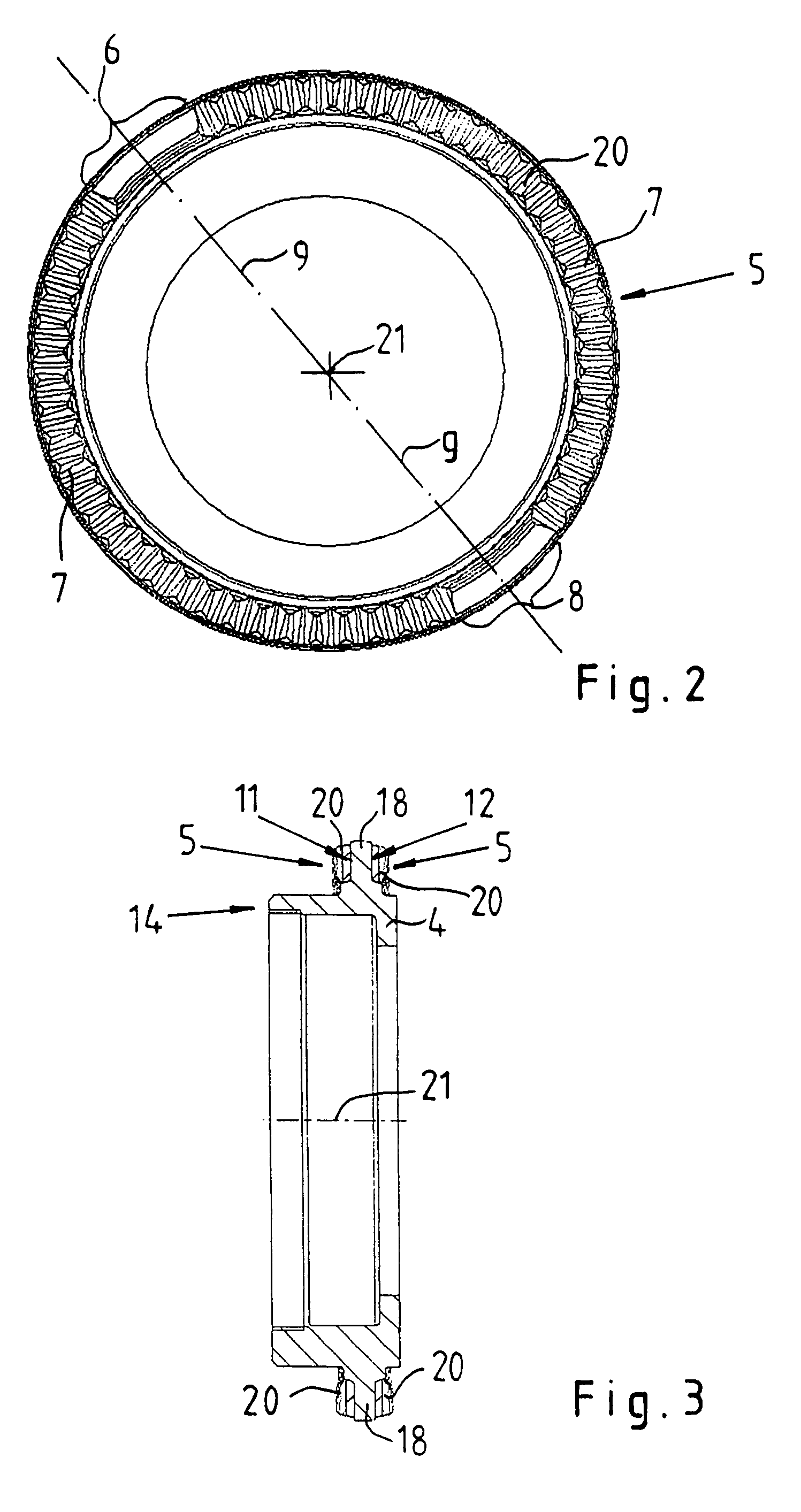
[0011]Preferably, the element with elastomeric properties is disposed around the whole of the circumferential region of the roller bearing and constructed ring-shaped. Regions of increased stiffness in the element with elastomeric properties may be produced, for example, owing to the fact that one or more regions of greater thickness or axial extent are provided at the element. If the space for mounting the element with elastomeric properties remains the same over its axial extent, this leads to a greater pre-tension in this region in the installed state.

Problems solved by technology

The roller bearing, however, is not equipped to compensate for bending moments, which are exerted on a shaft that is to be supported, by assuming an inclined position so that a slight tilting moment results and any jamming of the shaft is avoided.

Method used


Image

  • Roller bearing
  • Roller bearing
  • Roller bearing

Examples


Embodiment Construction

[0020]A roller bearing 1, surrounded axially and radially by a carrier 14, is shown in partial cross section in FIG. 1. The carrier 14 accommodates, without clearance, an external ring 15 of the roller bearing 1, which is constructed as an annular ball bearing. The annular ball bearing is constructed, for example, with two stationary seal rings 16 and supports a shaft 2 radially and axially in a rack 3, which is constructed as a steering gear housing 17. When in operation, tie rod forces existing at steered wheels of a motor vehicle, as a function of the deflection and further geometric and driving dynamic influences and forces, are exerted on the shaft 2, which is shown in the example as a ball-and-nut spindle of an electric power steering system. In order to ensure a minimum axial clearance of the shaft 2 in the steering gear housing 17 and avoid jamming the shaft 2 by the influencing factors remained, the carrier 14, which is constructed as a bearing ring 4, is supported and held...


PUM


Abstract

A roller bearing assembly for supporting a shaft axially and radially in a rack includes a roller bearing with a carrier, a portion of which is supported at the rack with an element with elastomeric properties being interposed between a support for the rack and the portion of the carrier. In order to indicate a roller bearing, which supports the shaft axially and radially, and makes an inclined position of the shaft possible without causing straining of the system of shaft, roller bearing and rack, the element with elastomeric properties, viewed in the tangential (circumferential) direction of the roller bearing, has at least a first region, the stiffness of which is different from that of the remaining tangential (circumferential) region.

Description

BACKGROUND OF THE INVENTION[0001]The invention relates to a roller bearing for supporting a shaft axially and radially in a rack, and more particularly, a roller bearing assembly which functions to inhibit straining of a system of the shaft, roller bearing and rack when subjected to a bending moment.[0002]A roller bearing is described in DE 601 03 257 12, especially for a steering column of motor vehicles for supporting a steering shaft radially and axially in a steering column. An inner ring of the roller bearing is supported over a compensating ring, which can be shifted to a limited extent axially, at a damping element of the steering column. The damping element may have elastomeric properties or an element with elastomeric properties, such as an axially elastic spring washer, is disposed between the damping element and the compensating ring. In this way, the inner clearance of the roller bearing can be eliminated and a durable, clearance-free and pre-loaded contact between the r...

Claims


Application Information

Patent Timeline
Patent Type & Authority Patents(United States)
IPC IPC(8): F16C27/06
CPCF16C27/066B62D1/16F16C19/06
Inventor BUDAKER, MARTINJUESCHKE, MICHAELWINTER, ROLANDHETZEL, OLIVERHAUCK, MICHAELWELLER, MANFRED
Owner ZF LENKSYSTEME GMBH
Learn More