Image forming device

a technology of image forming and forming parts, which is applied in the direction of instruments, electrographic process equipment, corona discharge, etc., can solve the problems of increasing the size increasing the cost, and complicated control of the image forming device, so as to reduce the number of parts and ensure the effect of reducing cos

Inactive Publication Date: 2010-03-23
SEIKO EPSON CORP
View PDF6 Cites 3 Cited by
  • Summary
  • Abstract
  • Description
  • Claims
  • Application Information

AI Technical Summary

Benefits of technology

[0008]An advantage of some aspects of the invention is that it provides an image forming device of a tandem type which makes it possible to surely and easily identify an image carrying body in which leakage is generated while providing reduction of the number of parts, reduction of cost, downsizing of the image forming device, and easiness of the control thereof.

Problems solved by technology

However, in the image forming device disclosed in Patent Document 1, the AC voltage power supply and DC voltage power source are respectively independently arranged for each color, so that there are various problems in that a number of parts is increased, cost is increased, the size of the image forming device is increased, and the control thereof is complicated, or the like.
However, when another object is contacted to the surface of the photoreceptor and damaged when the process unit including the photoreceptor is replaced by user, leakage is generated at the time of printing process and image forming defect is generated.
However, commonly providing the AC voltage power supply for each process unit for three colors makes it difficult to identify the process unit in which leakage is generated.

Method used


Image

  • Image forming device
  • Image forming device
  • Image forming device

Examples


Embodiment Construction

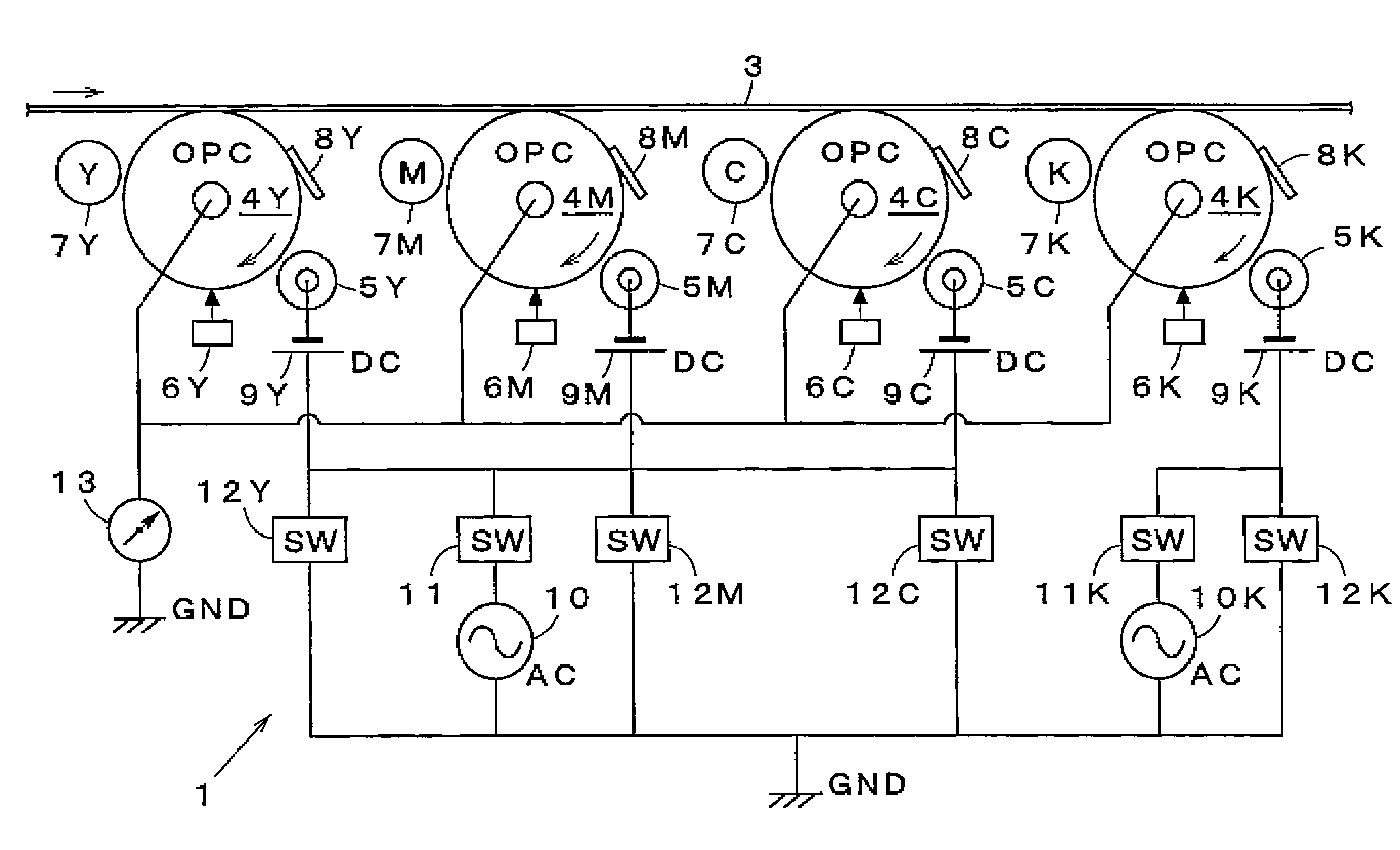
[0022]Hereinafter, the best mode for carrying out the invention will be described below with reference to the accompanying drawings.

[0023]FIG. 1 is a diagram schematically and partially showing an example of an embodiment of an image forming device according to the invention.

[0024]As shown in FIG. 1, an image forming device 1 of the example is equipped with at least each process unit 2Y, 2M, 2C, 2K for yellow (Y) color, magenta (M) color, cyan (C) color, and black (K) color, and an intermediate transfer belt 3.

[0025]Each process unit 2Y, 2M, 2C, 2K is arranged in a tandem manner in the order of Y color, M color, C color, K color from the upstream side toward the downstream side of the moving direction of the intermediate transfer belt 3 (from left side toward right side in FIG. 1). Note that the arrangement order for each color is not restricted to this and any arrangement order may be employed. However, in the description described below, each process unit 2Y, 2M, 2C, 2K shown in F...


PUM


Abstract

An image forming device. A direct voltage power supply is independently provided for each charging device for each color, and an alternating voltage power supply is commonly provided to the charging device for each color. A current detecting section detects current which flows between each image carrying body and each charging device. A control device judges that the image carrying body is damaged when a detected current value is not less than a preliminarily set specified value when a direct voltage is sequentially independently applied to the charging device for each color when leakage of charging voltage is generated.

Description

BACKGROUND[0001]1. Technical Field[0002]The present invention relates to a technical field of an image forming device such as an electrophotographic device, an electrostatic copier, a printer, a facsimile, and the like in which a DC power supply for a process unit for each color is independently arranged and an AC power supply is commonly arranged for the process units for three colors in the full-color image forming device of a tandem type.[0003]2. Related Art[0004]Heretofore, as an image forming device of a plurality of colors or full-color of an electrophotographic system, so cold an image forming device of a tandem type has been proposed in which a photoreceptor is arranged in a tandem manner in accordance with for each color and a toner image of each color formed on each photoreceptor is sequentially overlapped on an intermediate transfer medium or a transfer material in order to form a color image (for example, see JP-A-2001-324850 (hereinafter, referred to as Patent Document ...

Claims


Application Information

Patent Timeline
Patent Type & Authority Patents(United States)
IPC IPC(8): G03G15/00
CPCG03G15/0216G03G15/553
Inventor KAMOSHIDA, SHINICHI
Owner SEIKO EPSON CORP
Why Eureka
Try Eureka