
Outdoor deck lighting system

Inactive Publication Date: 2010-03-30
CPG INT
View PDF33 Cites 24 Cited by
  • Summary
  • Abstract
  • Description
  • Claims
  • Application Information

AI Technical Summary

Benefits of technology

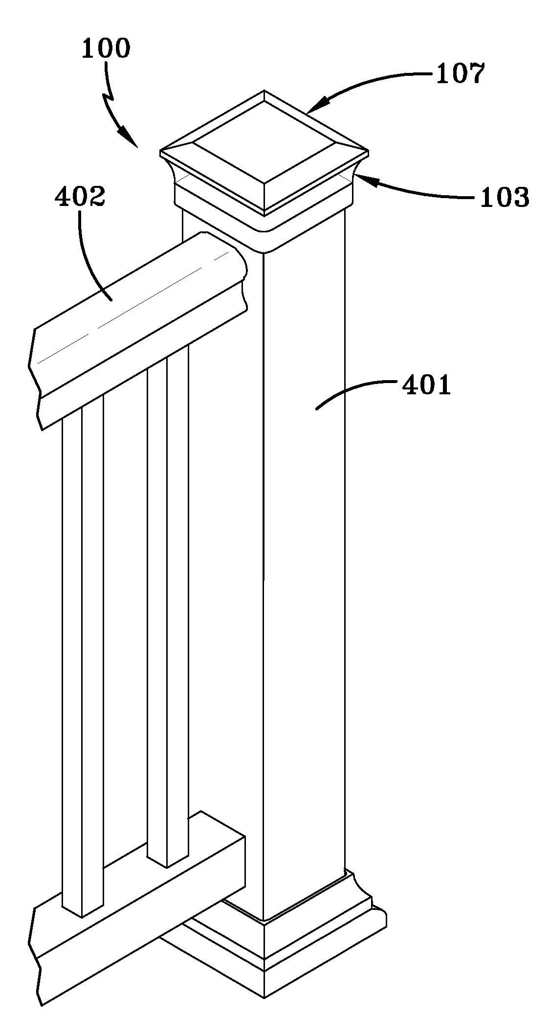
[0003]Exemplary embodiments of the present invention provide a lighting system for an outdoor deck area that provides sufficient lighting while at the same time adding to the aesthetic value of the area. Therefore, embodiments of the present invention may substantially hide the wires from view and incorporate the light housings into the deck components. More specifically, embodiments of the present invention may integrate the post light assembly materials into the existing post structure, thus providing a more seamless look and greater aesthetic appeal.
[0004]Embodiments of the present invention provide a lighting system that may be built specifically for the deck including the deck surface, railings, and posts to provide a total deck experience. In other words, the deck does not need to be torn up and rearranged to put in the lighting system; the deck may be manufactured to allow the easy installation of the lighting system.
[0005]The lighting system does not have to be tailor-made for every home, but can be manufactured at a high production rate and can be installed at existing homes or businesses. Also, the embodiments do not need to be installed by a specialized carpenter, but instead can be installed by the homeowner. In this way, cost is minimized.
[0006]Also, current post lights allow light to shine in an upward direction, thus wasting lighting efficiency by sending light into the night sky as well as into the eyesight of deck users. Embodiments of the present invention may focus light toward the deck itself, thus making more efficient use of the light lumens and preventing light from shining into the eyes of deck users.

Problems solved by technology

However, many decks do not have a sufficient lighting such that they can be enjoyed during the night time as well as the day time.
Furthermore, the decks that currently employ lighting systems must run the wiring on the surface of the posts, railings, and deck surface, providing a look that is not aesthetically pleasing.
Occasionally the wires are hidden by a conduit, but these materials are still not aesthetically pleasing.
Also, current post lights allow light to shine in an upward direction, thus wasting lighting efficiency by sending light into the night sky as well as into the eyesight of deck users.

Method used


Image

  • Outdoor deck lighting system
  • Outdoor deck lighting system
  • Outdoor deck lighting system

Examples


Embodiment Construction

)

[0012]Exemplary embodiments of the present invention are directed to the figures described herein.

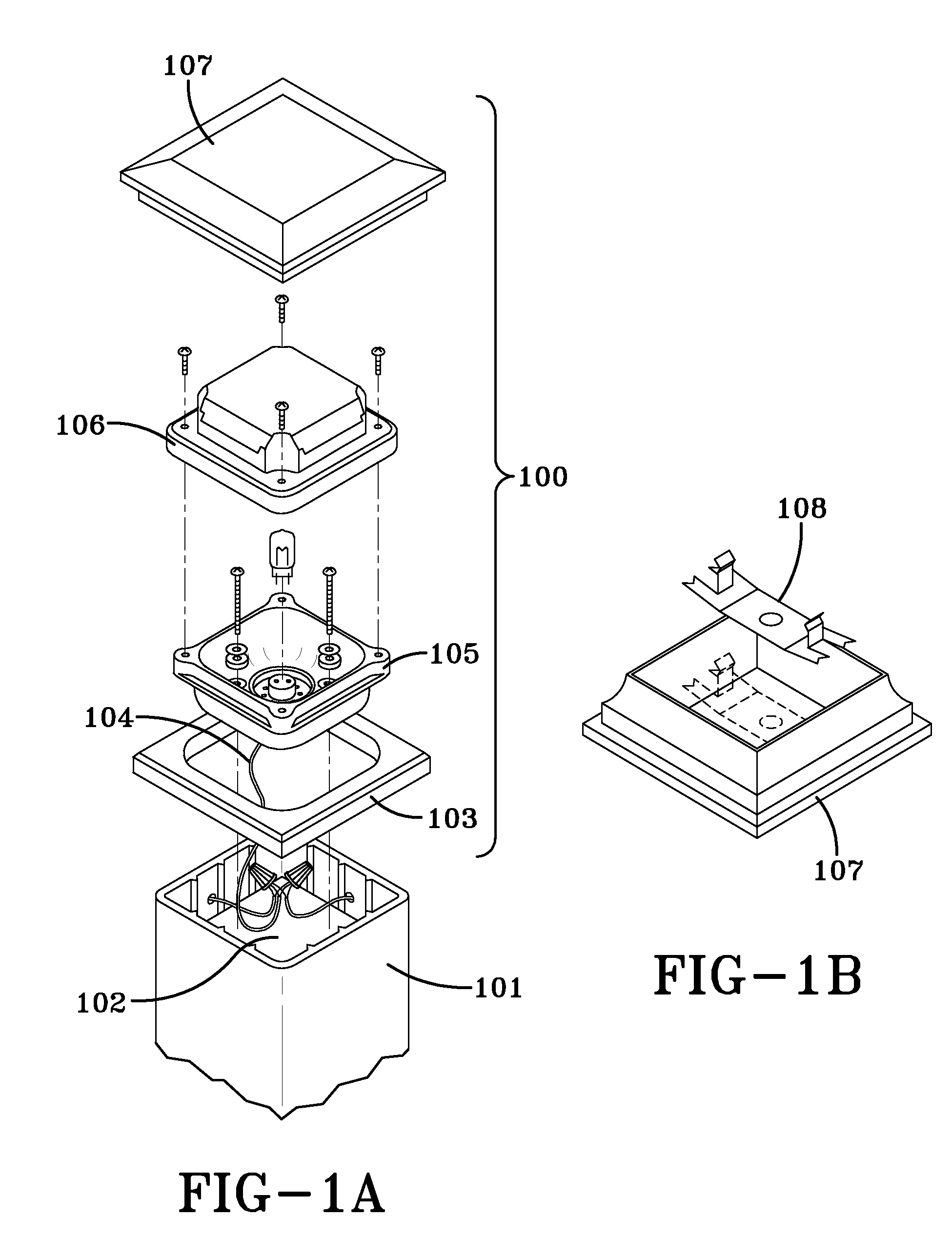
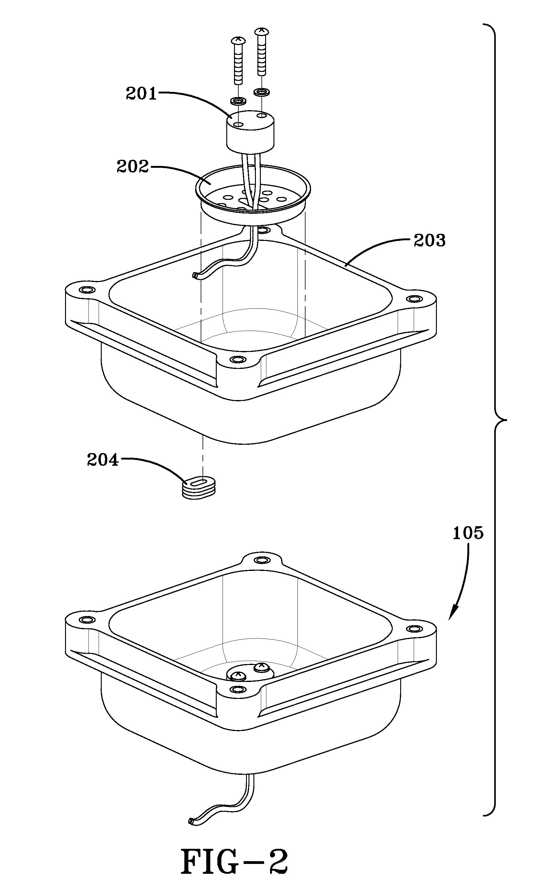
[0013]FIG. 1A is an exploded view of an exemplary embodiment of the post light assembly 100 and FIG. 1B shows the placement of a spring clip 108 within the post cap 107. In FIG. 1A, the post cover 101 fits over the post 102. The deck, post 102, and post cover 101 may be made from well known materials such as, but not limited to, wood, plastic, wood composites, and / or metal. The gap between the post cover 101 and the post 102 may allow wiring 104 to pass from underneath the deck surface to the top of the post 102 without being seen by a deck user. Wiring 104 may also enter the top of the post 102 by passing through a hole in the post cover 101. This technique may be used if the wiring 104 is traveling along the length of a rail rather than coming from below the deck surface.

[0014]The lens 103 sits on top of the post cover 101. In one exemplary embodiment, the lens 103 may be made of a t...


PUM


Abstract

A lighting assembly designed to fit within a rail post. The lamp post assembly focuses light toward the ground to prevent sending light into the night sky or into the eyes of users. The lamp assembly fits within a post to provide an aesthetically pleasing appearance. The lamp assembly can be installed in existing post configurations or installed with a new post. The lamp assembly also hides the wiring necessary for the lamp from view, thus providing a more aesthetically pleasing appearance.

Description

BACKGROUND AND SUMMARY OF THE INVENTION[0001]Embodiments of the present invention relate generally to lighting systems for outdoor deck areas, for lighting purposes as well as decorative purposes, and more particularly to a post light assembly which is integrated into a deck post.[0002]Outdoor deck areas are very popular as they add to the beauty of the home as well as provide a functional place to enjoy the outdoors. However, many decks do not have a sufficient lighting such that they can be enjoyed during the night time as well as the day time. Furthermore, the decks that currently employ lighting systems must run the wiring on the surface of the posts, railings, and deck surface, providing a look that is not aesthetically pleasing. Occasionally the wires are hidden by a conduit, but these materials are still not aesthetically pleasing. Also, post lights are typically separate assemblies which attach to the top of existing posts.[0003]Exemplary embodiments of the present invention...

Claims


Application Information

Patent Timeline
IPC IPC(8): F21S13/10
CPCF21V27/00F21V33/006E04F2011/1872F21S8/08F21V15/01F21V31/005F21W2111/08
Inventor PEVER, STEVE E.ROTHWELL, TIMOTHY C.
Owner CPG INT
Learn More