Fork alignment tool

Active Publication Date: 2010-04-06
MOTION PRO
View PDF21 Cites 14 Cited by
  • Summary
  • Abstract
  • Description
  • Claims
  • Application Information

AI Technical Summary

Benefits of technology

[0016]An advantage of the present invention is that it includes receiving cups which are configured to easily mate with the curved surfaces of the fork tubes and fork legs.
[0017]Another advantage of the present invention is that it includes connecting members which easily slide relative to each other to capture the spacing dimension of the fork tubes and fork legs at particular points along their length.
[0018]And another advantage of the present invention is that the connecting members are easily locked into position relative to

Problems solved by technology

If the suspension is not working properly, the handling characteristics of the motorcycle and the way it absorbs bumps are dramatically affected.
Additionally, some forks have been found to be out of alignment when received from the factory.
This misalignment largely results when the forks are

Method used


Image

  • Fork alignment tool
  • Fork alignment tool
  • Fork alignment tool

Examples


first embodiment

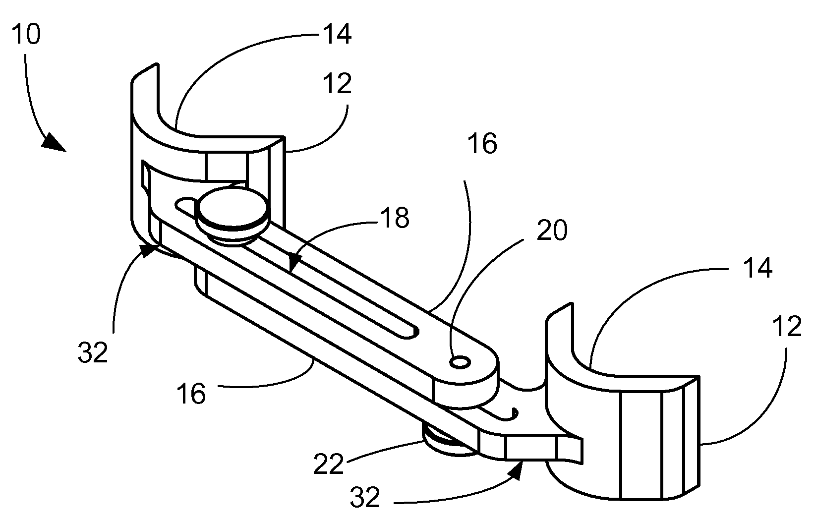
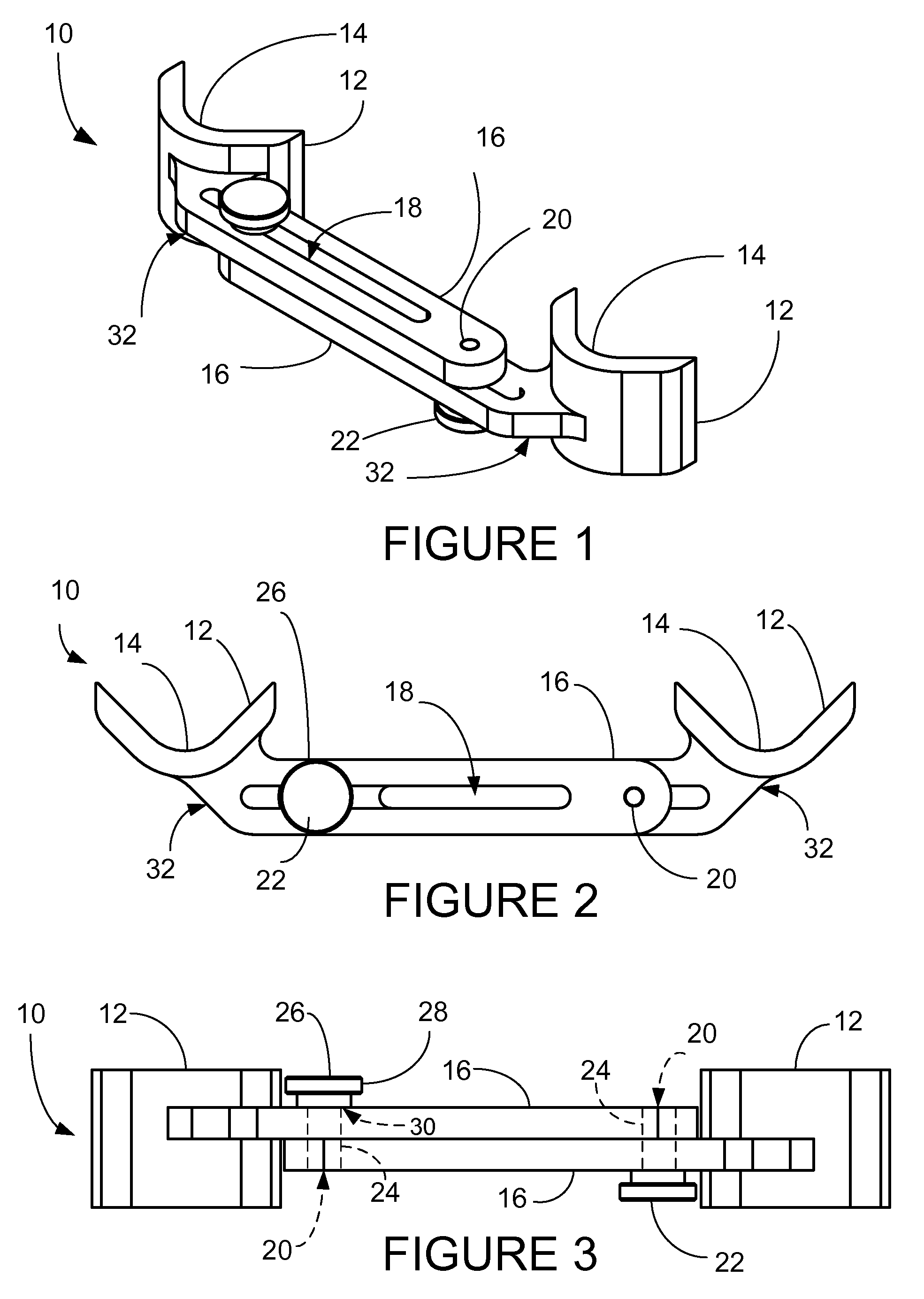
[0033]The present invention is an adjustable alignment tool for aligning the forks of a motorcycle, which will be referred to by the reference number 10, and thus, for simplicity, shall be referred to as alignment tool 10. the alignment tool 10 is illustrated in FIGS. 1-3, of which FIG. 1 is a perspective view, FIG. 2 is a top plan view, and FIG. 3 is a front plan view. FIG. 4 will also be referred to in the following discussion.

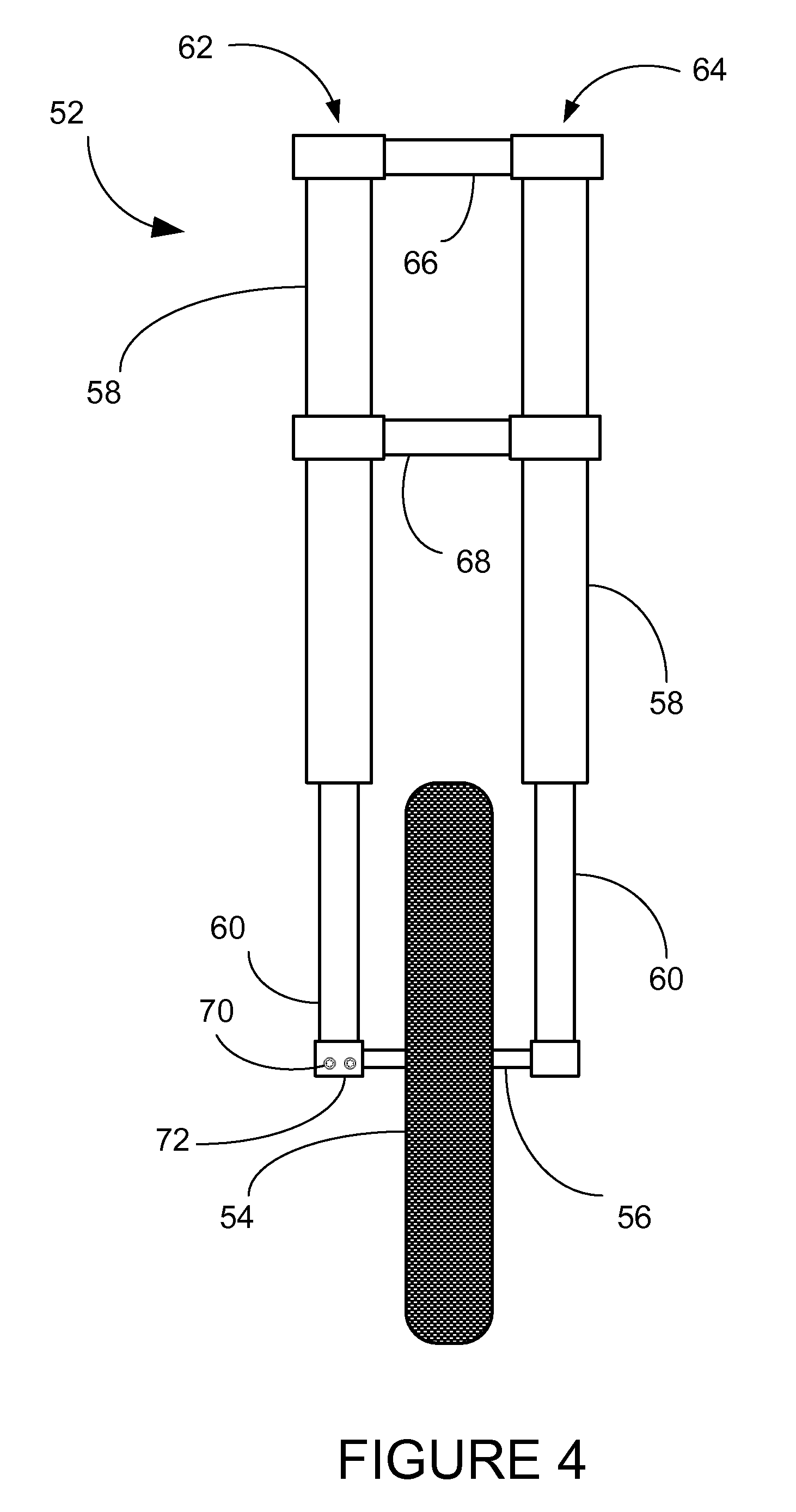
[0034]Generally, a first embodiment of the alignment tool 10 includes two receiving cups 12, which are each configured with a concave portion 14 which is shaped to receive the cylindrical shape of the fork tubes 58 (see FIG. 4). Each of the receiving cups 12 is connected to a slide bar 16, each of which preferably surrounds a slot 18. The slide bars 16 are laid adjacent to each other so that the included slots 18 are aligned. Each slide bar 16 is configured with a threaded screw hole 20. Two fasteners 22 are included which each have a male threaded portion 2...

embodiment 10

[0040]FIGS. 8-10 show an alternate embodiment of the alignment tool of the present invention, which shall be designated by the number 100. It utilizes many of the same elements as the earlier described embodiment 10, although certain elements are configured differently. In order to aid in understanding, elements which perform similar functions will be designated by the same element numbers as previously when possible.

[0041]It has been found that the cost to manufacture the component parts for the alignment tool 100 is decreased if the parts are made by extrusion. Thus it is advantageous that the connecting members 32 have a simplified profile when seen from a top plan view, as in FIG. 9. This can result in a pair of connecting members 32 having a first member 102 and a second member 104 which are a non-identical pair 106. It will also be obvious to one skilled in the art, that these connecting members could also be configured to be identical, as in the first embodiment 10, with appr...

embodiment 100

[0044]Also as before, the receiving cups 12 and slide bars 16 are preferably configured as part of the same combined structure, which will again be referred to here as a connecting member 32. It will be noted in the embodiment 100 illustrated here that there are two connecting members 32 included which are a non-identical pair 106, and their slide bar 16 portions are laid together with their slots 18 matching.

[0045]The fork alignment is conducted in the same manner as described above in relation to the earlier embodiment 10.

[0046]While various embodiments have been described above, it should be understood that they have been presented by way of example only, and not limitation.


PUM


Abstract

A tool is disclosed for alignment of forks in a wheeled vehicle. The tool includes a plurality of connecting members, each having a receiving cup, which is configured to receive the curvature of fork tubes of the forks of the vehicle, and a slide bar which attaches to a portion of the receiving cup. The connecting members are held in slidable relation to each other by at least one fastener when the fastener is loosened. The fastener can be tightened to lock the connecting members in fixed position relative to each other to capture the spatial separation dimension between the forks at a point along their length. Also disclosed is a method for achieving parallelism of forks in a wheeled vehicle.

Description

[0001]The following is a non-provisional patent application which claims priority to provisional application 60 / 829,101 filed Oct. 11, 2006 to the same inventor.TECHNICAL FIELD[0002]The present invention relates generally to tools for aligning mechanical parts and more particularly for aligning the forks of a motorcycle wheel.BACKGROUND ART[0003]Motorcycles are a popular means of recreation and transportation for a number of people. Being a two-wheeled vehicle, the suspension of the motorcycle is very important for proper operation. If the suspension is not working properly, the handling characteristics of the motorcycle and the way it absorbs bumps are dramatically affected. In order to insure that the suspension is working properly it is imperative that the forks must be aligned to be very parallel with each other. It is well known that every time the front wheel is removed and replaced the forks need to be aligned which in most cases is done by working the suspension up and down ...

Claims


Application Information

Patent Timeline
IPC IPC(8): G01B5/255G01B21/00
CPCG01B5/255G01B2210/18
Inventor THOMPSON, BOB
Owner MOTION PRO
Why Eureka
Try Eureka