Camera-based touch system

a touch system and camera technology, applied in the field of touch systems, can solve the problems of low resolution passive touch screen, touch screen suffer from a number of problems or shortcomings, and the computer display manipulation is virtually impossible, so as to achieve good operation, improve the frame rate of digital cameras, and improve the effect of resolution

Inactive Publication Date: 2010-04-06
SMART TECH INC (CA)
View PDF143 Cites 238 Cited by
  • Summary
  • Abstract
  • Description
  • Claims
  • Application Information

AI Technical Summary

Benefits of technology

[0032]The present invention provides advantages in that the passive touch system is of high resolution and allows actual pointer contacts with the touch surface as well as pointer hovers above the touch surface to be detected and corresponding output generated. Also, the present passive touch system provides advantages in that it does not suffer from parallax, image distortion, pointer position restrictions, image projection and scalability problems that are associated with prior art passive touch systems.
[0033]Furthermore, the present invention provides advantages in that since CMOS digital cameras are used, arbitrary pixel rows in the digital camera pixel arrays can be selected. This enables the frame rates of the digital cameras to be increased significantly. Also, since the pixel rows can be arbitrary selected, the pixel arrays can be exposed for greater durations for given digital camera frame rates allowing for good operation in dark rooms as well as well lit rooms.

Problems solved by technology

Therefore, these low-resolution passive touch screens are useful only for manipulating the computer or video display.
Without the ability to detect pointer contact with the touch screen, writing and drawing would be one continuos operation, and mouse clicks would not be possible thereby making computer display manipulation virtually impossible.
Unfortunately, these touch screens suffer from a number of problems or shortcomings as will be described.
Unfortunately, since mechanical pressure is required to bring both sheets into contact, analog resistive touch screens can only detect contact when there is sufficient pressure to bring the two sheets together.
Analog resistive passive touch screens also cannot sense when a pointer is hovering over the touch surface.
Therefore, in the case of analog resistive touch screens contact events and positions can only be detected when actual contacts are made with the touch surface.
Surface acoustic wave (SAW) touch screens typically provide for medium resolution and are not suitable for recording good quality writing.
Unfortunately, SAW touch screens exhibit noticeable parallax due to the thickness of the vibrating glass that is placed over the surface of the video or computer display.
Also, contact events and positions can only be detected when actual contacts are made with the glass surface.
As a result, capacitive touch screens cannot be used for recording writing or drawing but are suitable for selecting areas on the touch screen corresponding to computer generated buttons displayed on the video or computer display.
Capacitive touch screens also suffer disadvantages in that they are sensitive to temperature and humidity.
Existing passive touch screens of the types discussed above are all limited in the maximum size where they are still functional.

Method used


Image

  • Camera-based touch system
  • Camera-based touch system
  • Camera-based touch system

Examples


Embodiment Construction

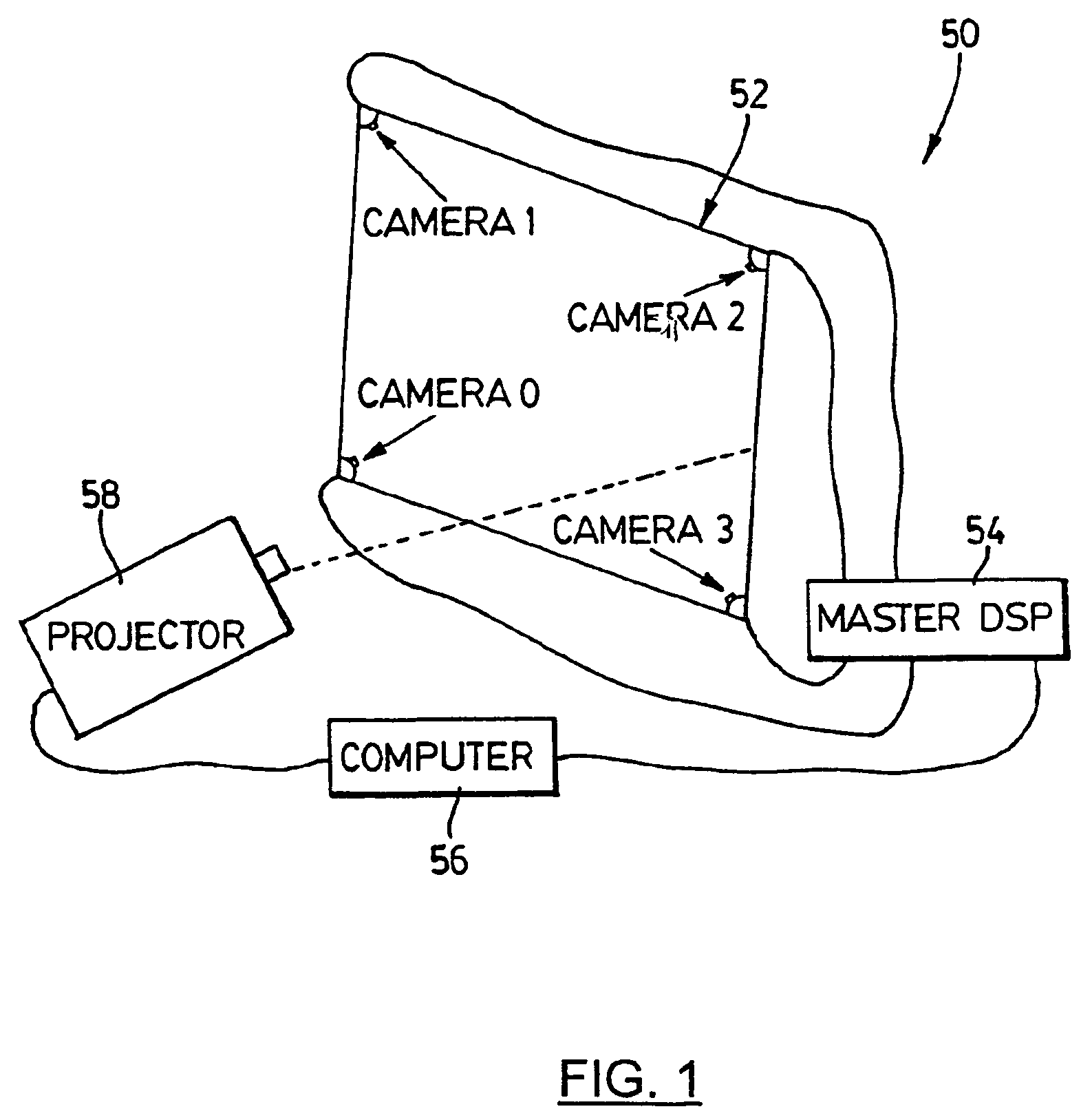
[0051]Turning now to FIG. 1, a camera-based touch system in accordance with the present invention is shown and is generally identified by reference numeral 50. As can be seen, touch system 50 includes a touch screen 52 coupled to a digital signal processor (DSP) based master controller 54. Master controller 54 is also coupled to a computer 56. Computer 56 executes one or more application programs and provides display output that is presented on the touch screen 52 via a projector 58. The touch screen 52, master controller 54, computer 56 and projector 58 form a closed-loop so that user contacts with the touch screen 52 can be recorded as writing or drawing or used to control execution of application programs executed by the computer 56.

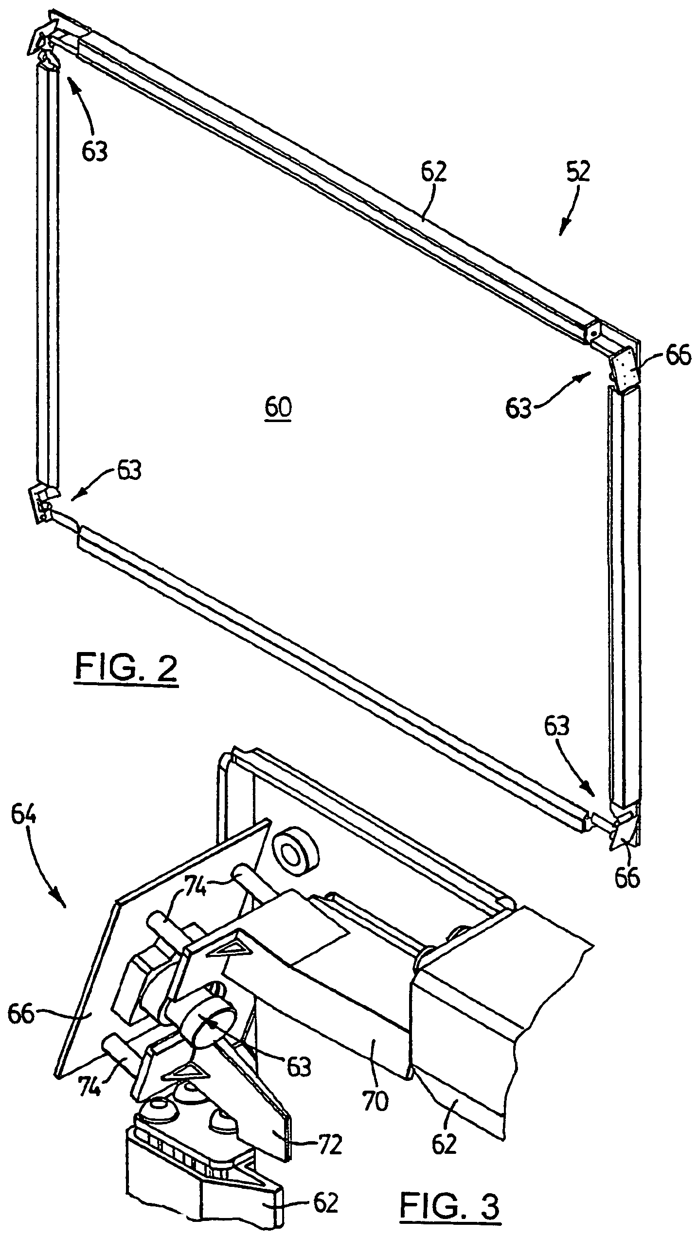
[0052]FIGS. 2 to 4 better illustrate the touch screen 52. Touch screen 52 includes a touch surface 60 bordered by a rectangular frame 62. Touch surface60 is in the form of a rectangular planar sheet of passive material. DSP-based CMOS digital cameras ...


PUM


Abstract

A camera-based touch system (50) includes a passive touch surface (60) and at least two cameras (63) associated with the touch surface. The at least two cameras (63) have overlapping fields of view (FOV) encompassing the touch surface. The at least two cameras (63) acquire images of the touch surface from different locations and generate image data. A processor (54) receives and processes image data generated by the at least two cameras to determine the location of the pointer relative to the touch surface when the pointer is captured in images acquired by the at least two cameras. Actual pointer contact with the touch surface and pointer hover above the touch surface can be determined.

Description

[0001]This application is a 371 of International Application No. PCT / CA01 / 00980, filed Jul. 5, 2001 (which designates the U.S. and was published in English on Jan. 10, 2002, as International Publication No. WO 02 / 03316 A1) which is a Continuation-In-Part of U.S. patent application Ser. No. 09 / 610,481, filed Jul. 5, 2000, now U.S. Pat. No. 6,803,906 B1. International Application No. PCT / CA01 / 00980, filed Jul. 5, 2001, also claims benefit of U.S. Patent Application No. 60 / 294,611, filed Jun. 1, 2001. The contents of all of these documents are incorporated herein by reference.TECHNICAL FIELD[0002]The present invention relates generally to touch systems and in particular to a camera-based touch system.BACKGROUND ART[0003]Touch systems are well known in the art and typically include a touch screen having a touch surface on which contacts are made using a pointer in order to generate user input. Pointer contacts with the touch surface are detected and are used to generate corresponding ou...

Claims


Application Information

Patent Timeline
Patent Type & Authority Patents(United States)
IPC IPC(8): G09G5/00G06F3/041G06T1/00G06F3/042G06T7/00G06T7/20G06T7/60
CPCG06F3/0428
Inventor MORRISON, GERALDHOLMGREN, DAVID
Owner SMART TECH INC (CA)
Why Eureka
Try Eureka