Wireless networking adapter and variable beam width antenna

a technology of wireless networking and antenna, which is applied in the direction of antennas, antenna details, electrical equipment, etc., can solve the problems of inconvenient use, small directional antennas, and negligible improvement of operating rang

Inactive Publication Date: 2010-04-13
HFIELD TECH
View PDF19 Cites 82 Cited by
  • Summary
  • Abstract
  • Description
  • Claims
  • Application Information

AI Technical Summary

Problems solved by technology

Such devices are undesirable because they are bulky, difficult to aim, and result in only negligible improvements in operating range.
Many of these devices use large directional antennas, such as a para

Method used


Image

  • Wireless networking adapter and variable beam width antenna
  • Wireless networking adapter and variable beam width antenna
  • Wireless networking adapter and variable beam width antenna

Examples


Embodiment Construction

)

[0018]The following detailed description of the preferred embodiments of the invention will be better understood when read in conjunction with the appended drawings. For the purposes of illustrating the invention, there is shown in the drawings embodiments which are presently preferred. It is understood, however, the invention is not limited to the precise arrangements and instrumentalities shown in the drawings.

[0019]To aid in describing the invention, directional terms are used in the specification and claims to describe portions of the present invention (e.g., front, rear, left, right, top and bottom, etc.). These directional definitions are intended to merely assist in describing and claiming the invention and are not intended to limit the invention in any way. In addition, reference numerals that are introduced in the specification in association with a drawing figure may be repeated in one or more subsequent figures without additional description in the specification in order...


PUM


Abstract

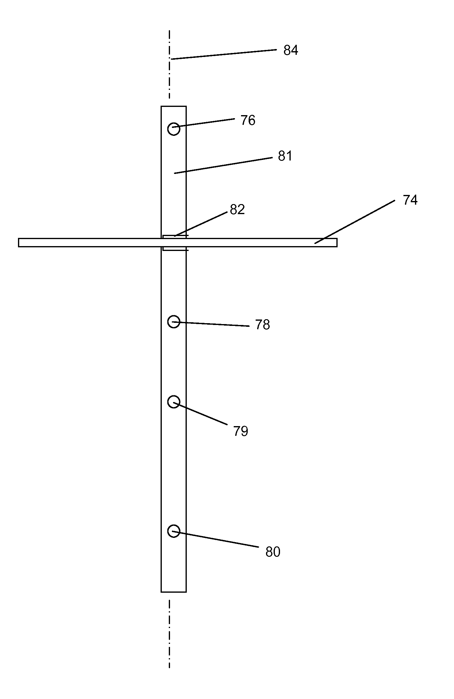
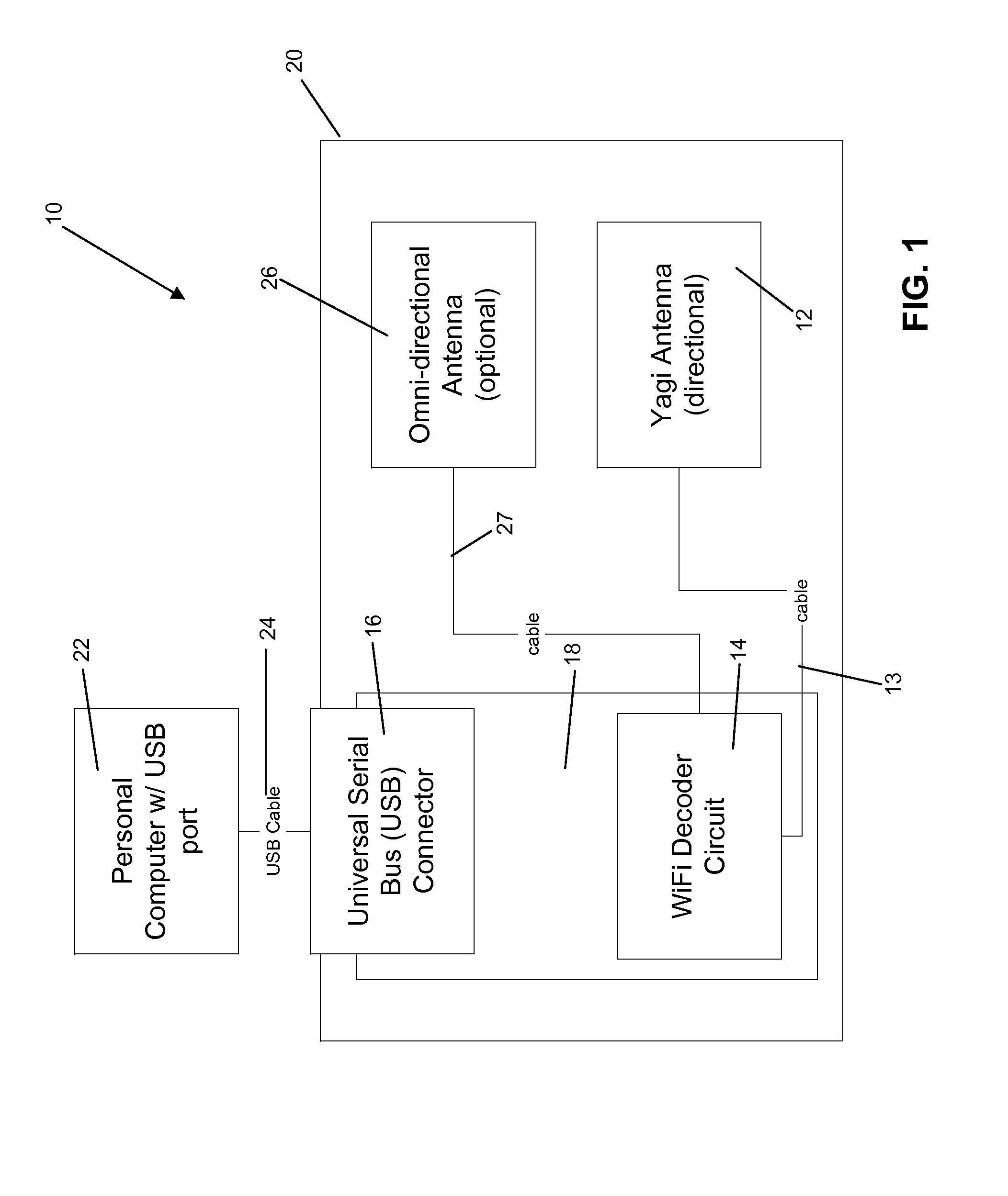
A wireless networking adapter that incorporates a Yagi-style directional antenna preferably includes at least one driver element positioned between a reflector element and at least two director elements. Another embodiment of the invention comprises a wireless access point having Yagi-style antenna that includes a driver that is adapted to rotate between a first position, in which the driver is in phase with the reflector an at least two directors, and a second position, in which the driver out of phase with a reflector and at least two directors.

Description

CROSS-REFERENCE TO RELATED APPLICATION[0001]This application claims the benefit of U.S. Provisional Application No. 60 / 677,095, filed on May 4, 2005, which is hereby incorporated by reference as if fully set forth herein.BACKGROUND OF THE INVENTION[0002]This invention relates to a wireless device for use in a local area network (LAN).[0003]Most current wireless networking adapters use an omni-directional antenna, which has a maximum operating range of 300 feet. In many operating environments, it is desirable to have a greater operating range.[0004]There have been some attempts to use directional antennas with wireless networking adapters. Some use an auxiliary antenna that is used as add-on to an existing wireless networking adapter. Such devices are undesirable because they are bulky, difficult to aim, and result in only negligible improvements in operating range.[0005]There have been some attempts to provide a wireless networking adapter with an integrated directional antenna. Man...

Claims


Application Information

Patent Timeline
IPC IPC(8): H01Q3/12
CPCH01Q3/18H01Q25/002H01Q19/30
Inventor MACDONALD, CURTIS
Owner HFIELD TECH
Why Eureka
Try Eureka