
Hand-held electric sealer having a detachable electric sealing module

a technology of electric sealing module and hand-held sealer, which is applied in the field of hand-held electric sealing module with detachable sealing module, can solve the problems of time-consuming for users and achieve the effect of convenient and instant solution

Active Publication Date: 2010-04-20
WELCOME
View PDF4 Cites 6 Cited by
  • Summary
  • Abstract
  • Description
  • Claims
  • Application Information

AI Technical Summary

Benefits of technology

"The present invention is a hand-held electric sealer with a detachable sealing module. The sealing module can be easily attached or detached from the electric sealer. The sealing module includes a module cover plate and a module seat plate which form an accommodation space for receiving a heating mechanism. The heating wire is welded with metal clips which are in contact with the conductive plates, which are in contact with the metal contacts touching the batteries. The invention solves the problem of a defective heating wire by simply replacing the existing sealing module with a new one. The technical effect of the invention is to provide a convenient and efficient solution for replacing the sealing module in case of a defect."

Problems solved by technology

However, in case the sealing mechanism needs to be removed and replaced because, for example, the heating wire has worn out, it is time consuming for the user to take away the relevant components from the casing and put them back into the casing, together with a functional heating wire.

Method used


Image

  • Hand-held electric sealer having a detachable electric sealing module
  • Hand-held electric sealer having a detachable electric sealing module
  • Hand-held electric sealer having a detachable electric sealing module

Examples


first embodiment

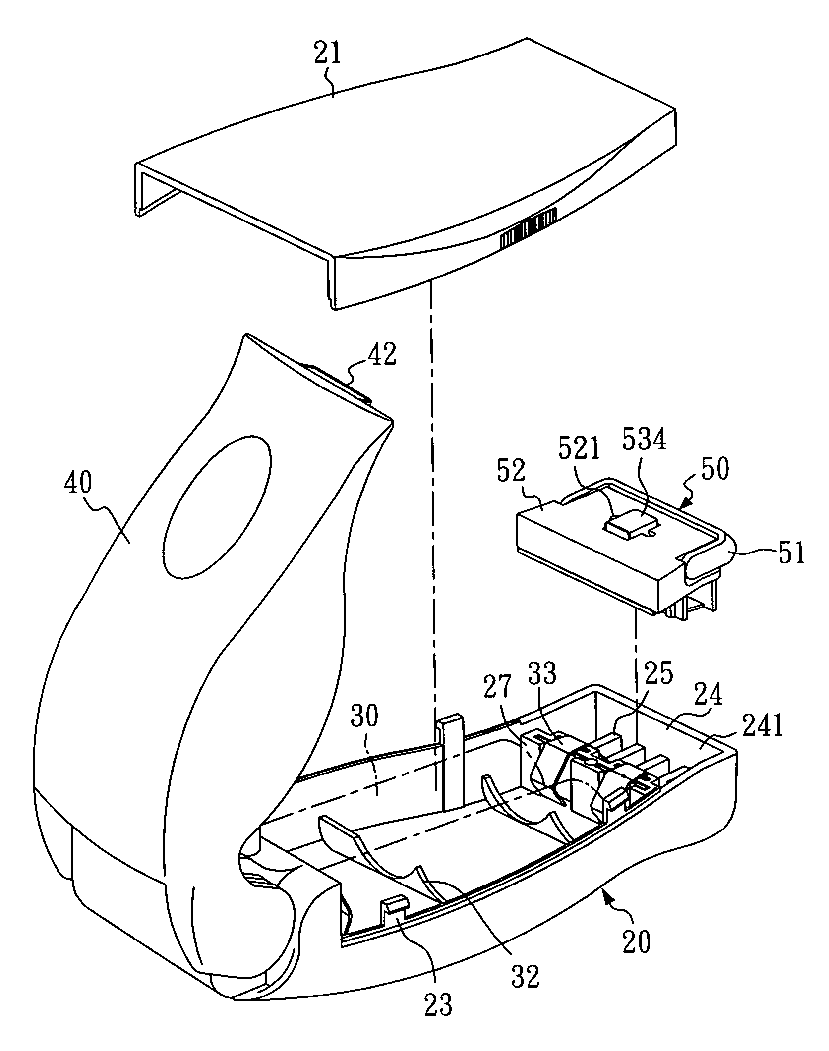
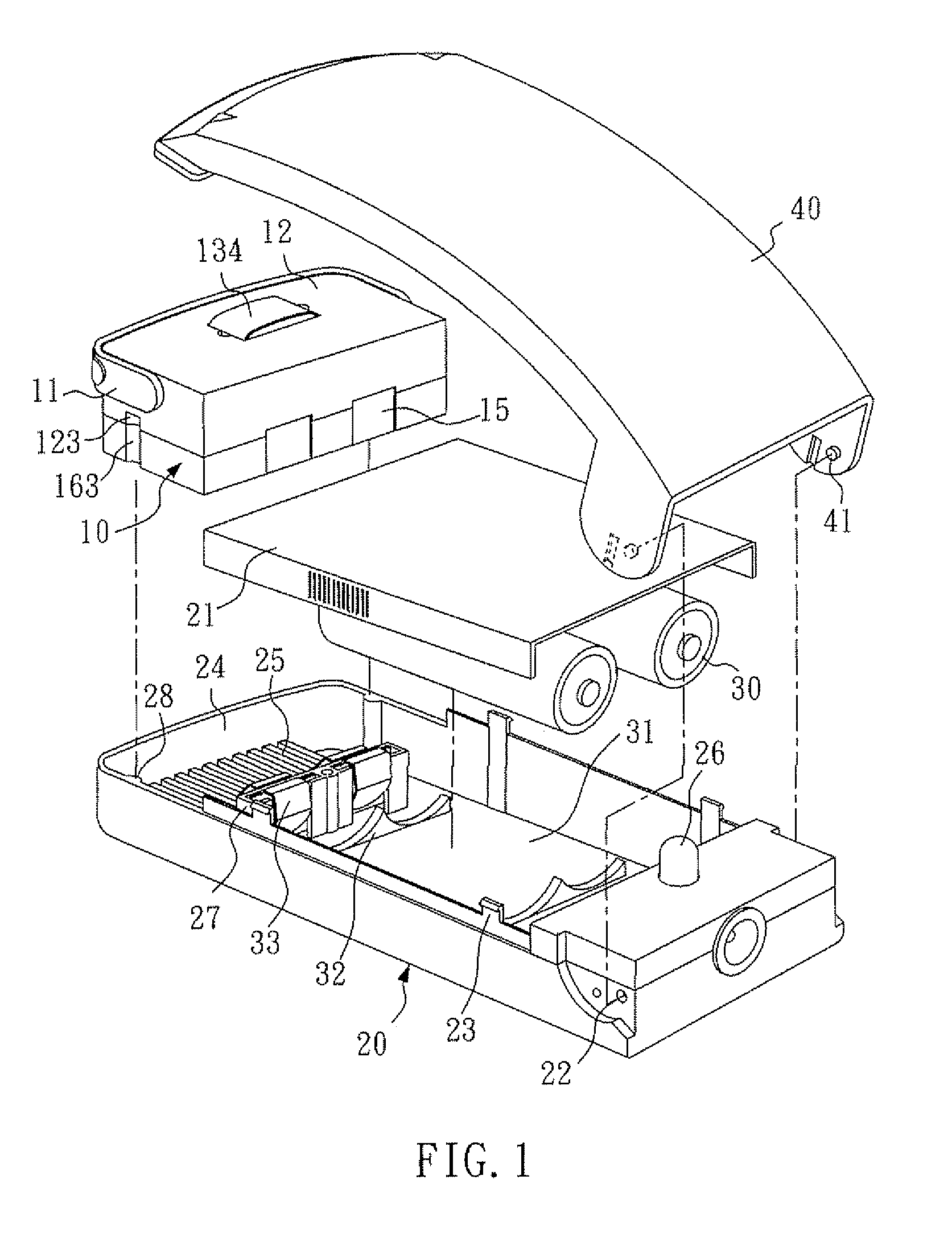
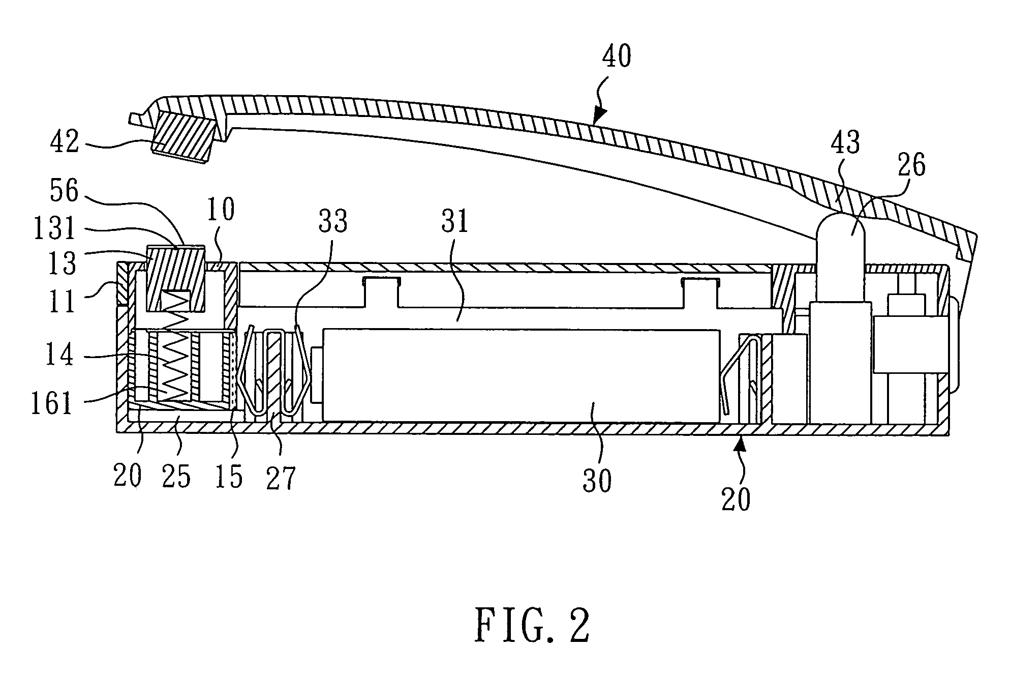
[0018]As shown in FIGS. 1 and 2, the hand-held electric sealer according to the present invention is equipped with a detachable sealing module 10 which, as a single unit, can be attached to or detached from a casing 20 of the electric sealer conveniently. The casing 20 has a module chamber 24 located at the front end of the casing 20 and a battery chamber 31 beside the module chamber 24, where the chambers 24, 31 are separated by a partition plate 27. The module chamber 24 receives the sealing module 10 which is supported by ribs 25 formed integrally with the casing 20, and where the battery chamber 31 receives batteries 30 which are supported by a battery holder 32 formed integrally with the casing 20. The partition plate 27 is also formed integrally with the casing 20, having metal contacts 33 attached to the partition plate 27. A battery cover plate 21, for protecting the batteries 30, is mounted on the casing 20, such that hooks 23 of the casing 20 engage with recesses (not show...

second embodiment

[0023]Generally speaking, the electric sealer according to the present invention also comprises a casing 20 having a module chamber 24 and a battery chamber 31 separated by a partition plate 27 on which metal contacts 33 are mounted. The module chamber 24 receives the sealing module 50 which is supported by ribs 25.

[0024]The sealing module 50, as shown in FIGS. 9 to 11, includes a module cover plate 52 and a module seat plate 56 affixed together so as to form an accommodating space 57 for receiving a heating mechanism. The heating mechanism includes a heat-insulating base 53, a heating wire 531, two metal clips 532, and a heat-resistant cover sheet 534, where the heating wire 531 is disposed along the top of the heat-insulating base 53 and is welded with the metal clips 532. The module seat plate 56 is provided with slots 562 for securing conductive plates 55, and a spring holder 561 for securing a spring 54. The metal clips 532 can electrically contact the conductive plates 55. The...


PUM

PropertyMeasurementUnit
conductiveaaaaaaaaaa
heat-resistantaaaaaaaaaa
currentaaaaaaaaaa

Abstract

A hand-held electric sealer having a detachable sealing module, comprises a casing having a module chamber located at the front end of the casing and a battery chamber beside the module chamber, a sealing module unitarily attached to or detached from the module chamber, and a press bar pivotally fixed at the rear end of the casing. Also disclosed is a detachable sealing module for use with the hand-held electric sealer, comprising a module cover plate and a module seat plate which form an accommodating space for receiving a heating mechanism, where the top portion of the heating mechanism protrudes from the module cover plate upon being biased by a spring secured in the module seat plate.

Description

BACKGROUND OF THE INVENTION[0001]1. Field of the Invention[0002]The present invention relates to electric sealers and, more particularly, to a hand-held electric sealer having a detachable sealing module.[0003]2. Description of Related Art[0004]Conventionally, a hand-held electric sealer used for sealing a plastic bag, such as the one disclosed in U.S. Pat. No. 6,326,594 issued to Chang et al., comprises, among other elements, a casing and a sealing mechanism which produces heat for sealing plastic bags. The sealing mechanism is mounted in the casing and includes a heat-insulating base, a heating wire, two metal locating plates, a heat-resistant cover sheet, and a compression spring. The compression spring has a bottom end fixed in the spring holder located in the casing, such that the sealing mechanism is supported on the compression spring and can be moved up and down relative to the casing. However, in case the sealing mechanism needs to be removed and replaced because, for examp...

Claims


Application Information

Patent Timeline
Patent Type & Authority Patents(United States)
IPC IPC(8): H05B3/02B29C65/22B65B51/10
CPCB29C65/228B29C66/43121B29C66/8161B29C66/8167B29C66/8324B29C66/8618B29C66/1122B29C66/81821B29C65/224B29C65/225Y10T156/18B29C66/818B65B51/148B29C65/00B29C66/8221B29C66/849B29C66/81422B29C66/8742B29C65/04B65B51/22
Inventor CHOU, AMMYCHANG, RICHARD
Owner WELCOME
Learn More