
Retrofit doorlight blind assembly

a technology for doorlight blinds and assemblies, applied in the direction of wing arrangements, door/window protective devices, curtain suspension devices, etc., to achieve the effect of reducing inventory, facilitating subsequent changes to the assembly, and being easy to attach and remove from the fram

Inactive Publication Date: 2006-08-01
ODL
View PDF49 Cites 28 Cited by
  • Summary
  • Abstract
  • Description
  • Claims
  • Application Information

AI Technical Summary

Benefits of technology

[0009]In a second aspect of the invention, the frame includes multipurpose blind guides. First, the guides have a C-shaped section that surrounds the edges of the blind to guide the blind during raising and lowering. Second, the guides secured the glass panel within the frame. Third, the guides hide the mechanism from view. And, fourth, the guides reinforce the frame.
[0011]In a fourth aspect of the invention, the blind snap-fits into the assembly frame so that the blind is easily attached to and detached from the frame. Specifically, the blind assembly includes a catch that snaps into a slot on the header. This feature reduces inventory, because assemblies can be made to order by snapping any one of a plurality of blinds (e.g. having a desired feature such as color) into a common frame. This feature also facilitates subsequent changes to the assembly, such as replacing a blind having one feature with a blind have a different feature.
[0012]In a fifth aspect of the invention, the blind actuator rod includes an improved technique for securing the actuator cords. More specifically, small barrels are mounted transversely in the rod; and the actuator cords are secured within the barrels. This technique eliminates the prior art need to glue the cords to the barrel, with the attendant manufacturing difficulties and costs.

Problems solved by technology

Third, the guides hide the mechanism from view.

Method used


Image

  • Retrofit doorlight blind assembly
  • Retrofit doorlight blind assembly
  • Retrofit doorlight blind assembly

Examples


Embodiment Construction

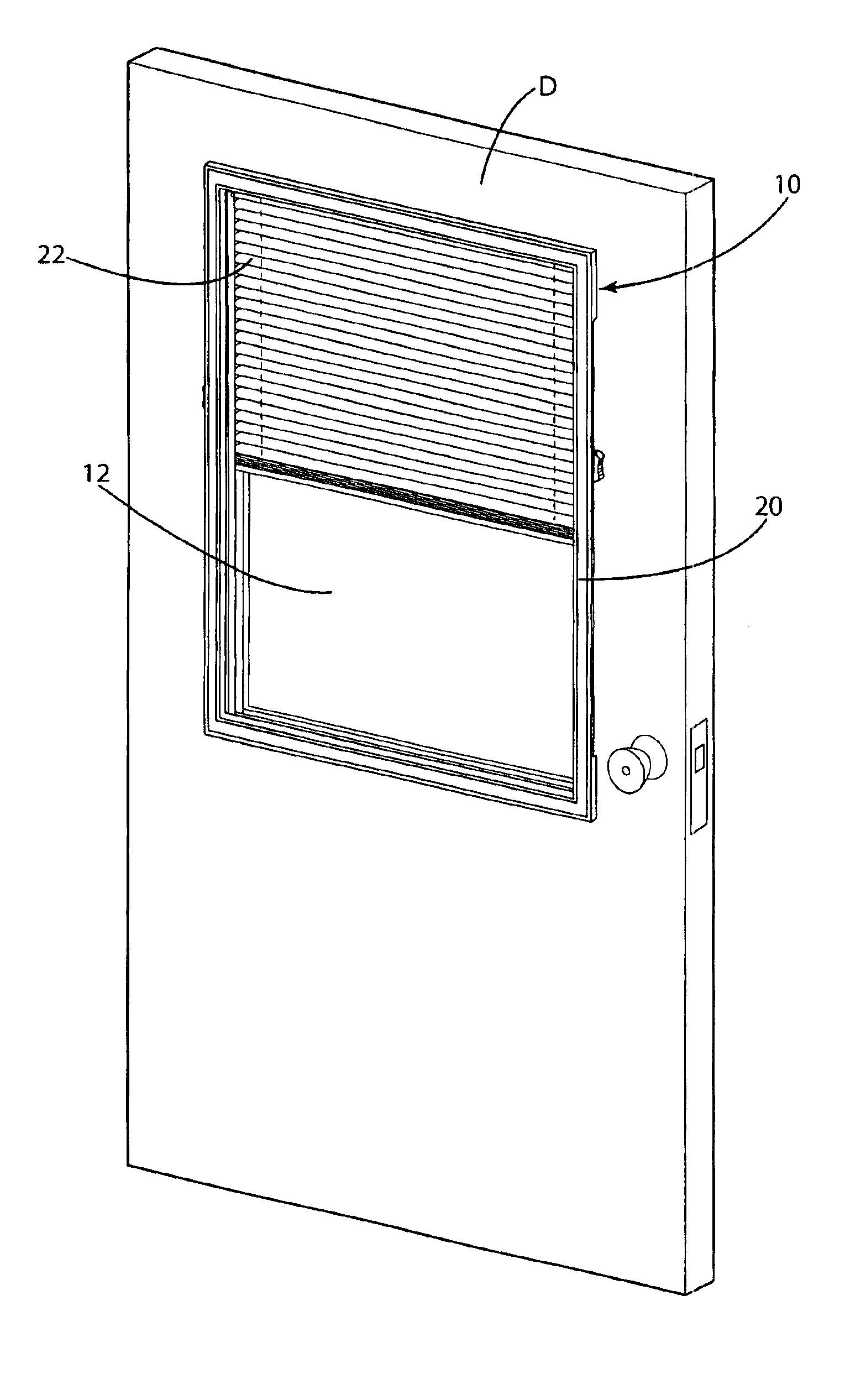
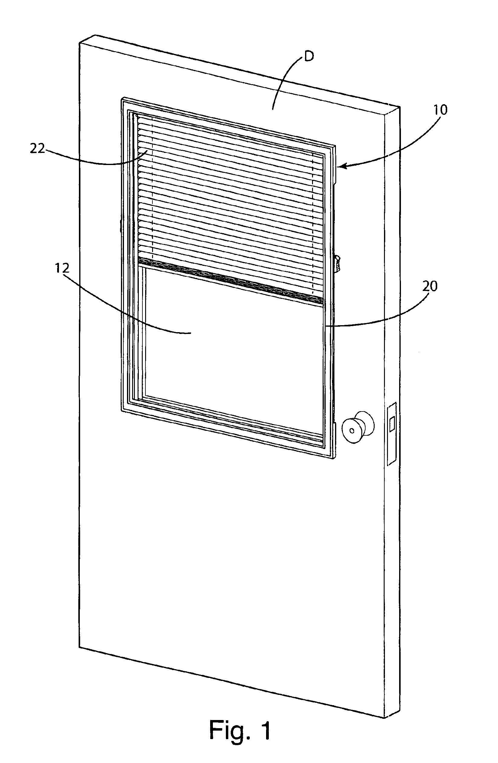
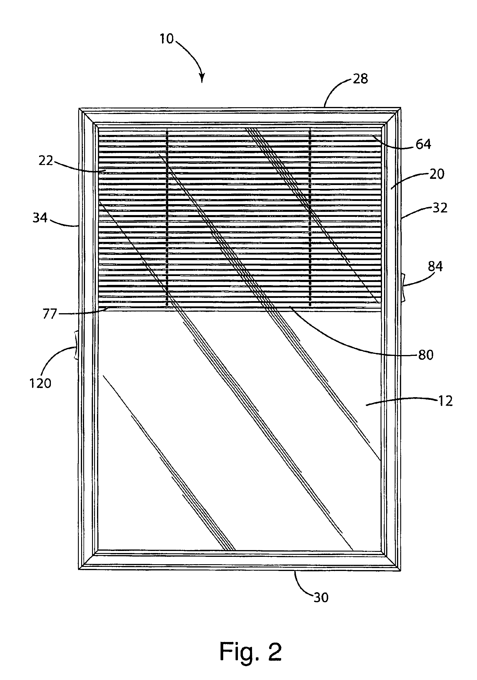
[0024]A blind assembly according to a preferred embodiment of this invention is illustrated in FIGS. 1-3 and generally designated 10.

I. Structure

[0025]The assembly 10 includes a window pane 12, a frame 20, a set of blinds 22, a tilt control mechanism 24, and a height control mechanism 26. The assembly 10 is described for installation over a door D and doorlight L. However, the assembly 10 may be installed over other, various window types.

[0026]The frame 20 is preferably molded of plastic, although other materials, such as wood or metal, may be used. The frame 20 includes top and bottom sides 28 and 30 and left and right sides 32 and 34. The sides 28, 30, 32, and 34 meet at right angles and form a rectangle, although the frame 20 may include a larger or smaller number of sides and form other shapes, such as a triangle or octagon. A pane opening 36 is defined in the center of the frame 20. Although the frame will be described with reference to a rectangular pane opening 36, and accord...


PUM


Abstract

A retrofit blind assembly for a doorlight. The assembly includes a frame, a transparent panel, and a blind snap-fitted to the frame. The blind actuator includes gears and a toothed belt for positive, non-slip actuation. A pair of blind guides are mounted on the opposite sides of the frame to receive and guide the opposite ends of the blind. The mounting system includes a pair of brackets that can be secured between the doorlight and the door and upon which the assembly can be hung. The mounting system also includes a pair of movable catches on the lower portion of the frame snap that can be locked behind the doorlight to secure the lower end of the assembly.

Description

[0001]This is a continuation of application Ser. No. 10 / 268,545, filed Oct. 10, 2002 (now U.S. Pat. No. 6,817,401).BACKGROUND OF THE INVENTION[0002]The present invention relates to window blind assemblies and, more particularly, to a blind assembly particularly well adapted for mounting over doorlights.[0003]Window units incorporating blinds are well known in the prior art. These units include two panes of glass an a blind assembly sandwiched between the two panes. The blind assemblies include mechanisms both for raising and lowering the blinds and for tilting the blind slats. The units include slides or knobs or handles coupled to the mechanisms and accessible from the outside of the unit. When a window unit is especially designed or adapted for installation in a door, the unit is referred to as a doorlight.[0004]Because it is difficult, time-consuming and costly to replace existing doorlights with doorlights having integral blinds, retrofit assemblies have been developed for retro...

Claims


Application Information

Patent Timeline
IPC IPC(8): A47H1/00E06B7/28E06B9/304E06B9/32
CPCE06B7/28E06B9/32E06B9/304
Inventor EVELAND, MIKE S.KROCHMAL, ANDREW R.DORCIC-LECHENET, MICHELE M.
Owner ODL
Learn More