Battery and battery module

a battery and module technology, applied in the field of batteries, can solve the problems of reducing the mass energy density of the battery, affecting the performance of the battery, and corresponding increase in the parts count, etc., and achieves the reduction of the parts count of the battery, the reduction of the lightness in the weight of the plastic battery case, and the effect of sufficient hermeticity

Inactive Publication Date: 2010-04-27
SANYO ELECTRIC CO LTD
View PDF6 Cites 3 Cited by
  • Summary
  • Abstract
  • Description
  • Claims
  • Application Information

AI Technical Summary

Benefits of technology

[0010]Accordingly, it is an object of the present invention to provide a battery and a battery module that have sufficient hermeticity and high reliability, while being lightweight and rigid, and moreover achieve lower parts count and low cost.
[0019]With the configuration of the battery according to the present invention, necessary rigidity is ensured and moreover sufficient hermeticity is achieved without substantially impairing the lightness in weight of the plastic battery case. Moreover, when the internal pressure of the battery rises to a certain level, the sealing portion at which the sealing members are melt-bonded to each other is split open and the gas is released outside. In other words, the sealed portion of the sealing members with each other function as a safety valve and serves as a gas release passage that can guide the gas in the battery to the outside. Thus, by making use of the sealed portion at the opening portion of the battery case, a gas release mechanism in the event of internal pressure increase is formed without additionally providing a safety valve. Accordingly, the parts count of the battery is reduced, and thereby the battery becomes lighter in weight and lower in cost.
[0020]Thus, the present invention makes it possible to provide a battery and a battery module that have sufficient hermeticity and high reliability, while being lightweight and rigid, and moreover achieve lower parts count and low cost.

Problems solved by technology

A problem with the use of a metallic can is that although it has rigidity against impact from the outside, metal has greater specific gravity than plastic or the like, resulting in a lower mass energy density of the battery.
However, it tends to show insufficient strength to resist impact from the outside because the aluminum laminate sheet is soft, and in order to supplement the insufficient strength, it has been necessary to provide additional means such as covering the battery with an outer cover such as a housing having rigidity.
In addition, when lithium-ion batteries employing a battery case made of a metallic can or an aluminum laminate are used to construct a battery module, it has been necessary to use a housing and battery module components that are made of metal or plastic to construct the battery module using the batteries, and the corresponding increase in the parts count has been a problem.
However, the use of plastic battery cases for lithium-ion batteries is particularly problematic because plastic does not provide complete hermeticity.
Specifically, since the lithium-ion battery uses an electrolyte solution containing an organic solvent, entry of moisture through the wall of the plastic battery case and leakage of gas generated from the organic solvent of the electrolyte solution through the wall can be significant causes of poor durability of the battery.
Nevertheless, the techniques as disclosed in Japanese Published Unexamined Patent Application Nos. 2002-56829 and 10-106513 are far from satisfactory in terms of weight reduction and cost reduction because no particular improvements are observed in terms of parts count reduction.

Method used


Image

  • Battery and battery module
  • Battery and battery module
  • Battery and battery module

Examples


embodiments

[0068]Hereinbelow, with reference to the drawings, the present invention is described in further detail based on certain embodiments and examples thereof. It should be construed, however, that the present invention is not limited to the following embodiments and examples, but various changes and modifications are possible without departing from the scope of the invention.

[0069]Preparation of Positive Electrode

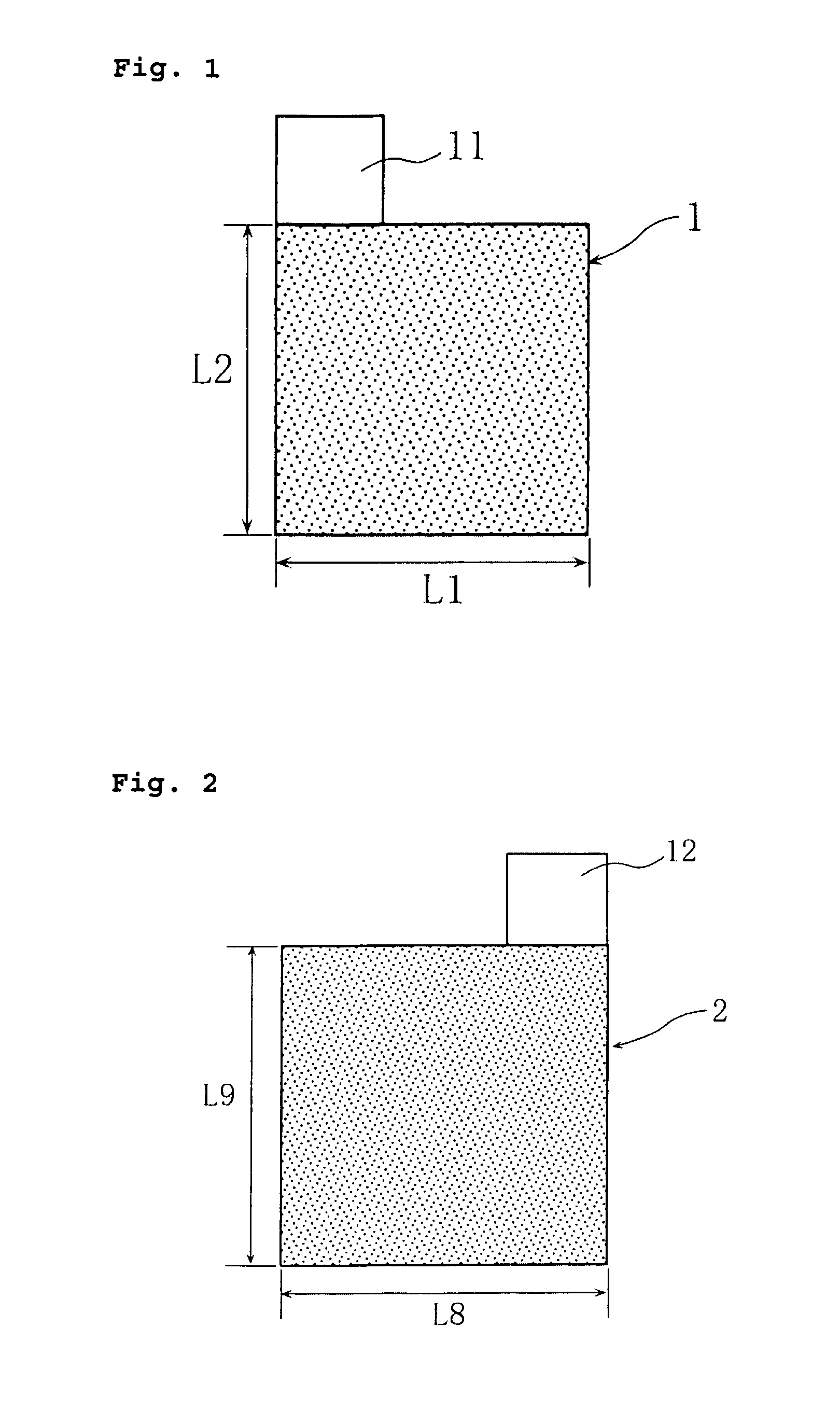
[0070]90 mass % of LiCoO2 as a positive electrode active material, 5 mass % of carbon black as a conductive agent, and 5 mass % of polyvinylidene fluoride as a binder agent were mixed with a N-methyl-2-pyrrolidone (NMP) solution as a solvent to prepare a positive electrode mixture slurry. Thereafter, the resultant positive electrode mixture slurry was applied onto both sides of an aluminum foil (thickness: 15 μm) serving as a positive electrode current collector, except for the region to which a positive electrode current collector tab would be welded. Then, the material was dr...

example 1

[0085]A battery fabricated in the same manner as described in the foregoing embodiment was used as the battery of Example 1.

[0086]The battery thus fabricated is hereinafter referred to as a battery A1.

[0087][Charge-discharge Test for the Battery]

[0088]The battery was charged at a constant current of 1.0 It (2.5 A) to 4.2 V, and thereafter discharged at a constant current of 1.0 It (2.5 A) to 2.5 V.

[0089]In the charge-discharge test, the average discharge voltage was 3.7 V, and the discharge capacity was 2.5 Ah.

[0090]Effects of the Battery

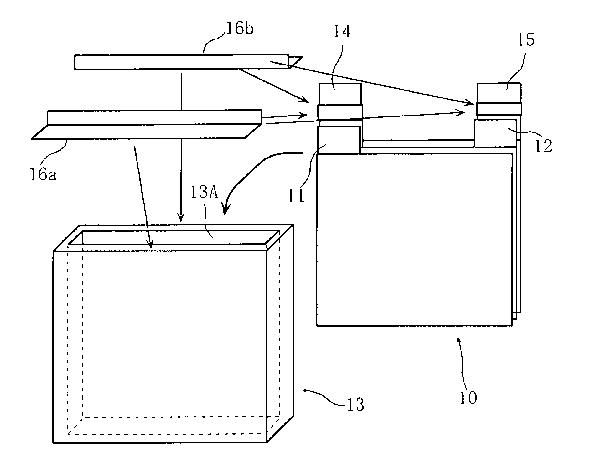
[0091]In the battery A1, a power-generating element containing the stacked electrode assembly 10 and the electrolyte solution is disposed in the accommodating space of the battery case 13 made of polypropylene resin. The positive electrode current collector tabs 11 / positive electrode current collector lead 14 and the negative electrode current collector tabs 12 / negative electrode current collector lead 15 connected to the positive electrode 1 and th...

example 2

[0096]A battery module fabricated in the same manner as described in the foregoing embodiment was used as the battery module of Example 2.

[0097]The battery module thus fabricated is hereinafter referred to as a battery module B1.

[0098][Charge-discharge Test for the Battery Module]

[0099]The battery was charged at a constant current of 1.0 It (2.5 A) to 21 V and thereafter discharged at a constant current of 1.0 It (2.5 A) to 12.5 V.

[0100]In the charge-discharge test, the average discharge voltage was 18.5 V, and the discharge capacity was 2.5 Ah.

[0101]Effects of the Battery Module

[0102]The configuration of the battery module B1 is as follows. The battery module case 20 has five accommodating spaces formed therein, and each one of the power-generating elements, which comprises the stacked electrode assembly 10 and the electrolyte solution, is disposed in a respective one of the accommodating spaces. The positive electrode current collector tabs 11 / positive electrode current collector ...


PUM

PropertyMeasurementUnit
thicknessaaaaaaaaaa
thicknessaaaaaaaaaa
widthaaaaaaaaaa

Abstract

A power-generating element containing a stacked electrode assembly (10) and an electrolyte solution is disposed in an accommodating space of a plastic battery case (13). The entirety of the battery case (13) is enclosed air-tightly and liquid-tightly in an outer cover made of an aluminum laminate. An opening (13A) of the battery case (13) is sealed by sealing members (16a, 16b) disposed and melt-bonded so as to cover an opening (13A) of the battery case 13 and to sandwich current collectors (14, 15) of the power-generating element from both sides. The outer cover is sealed at at least a location corresponding to the opening (13A) of the battery case (13).

Description

BACKGROUND OF THE INVENTION[0001]1. Field of the Invention[0002]The present invention relates to batteries such as prismatic lithium-ion batteries used for low-rate discharge backup power sources, and battery modules in which a plurality of such batteries are connected to each other. More particularly, the invention relates to batteries and battery modules that use a lightweight and rigid battery case made of plastic and that achieve high reliability and low cost.[0003]2. Description of Related Art[0004]Power sources used for low-rate discharge backup applications, for example, are hermetically sealed in a limited space and are therefore desired to be compact and lightweight, as well as being low in cost. As one type of batteries that can meet such requirements, lithium-ion batteries, which have high energy density and high power density, have been used widely in recent years. Lithium-ion batteries have been used as secondary batteries for various types of mobile devices.[0005]For t...

Claims


Application Information

Patent Timeline
Patent Type & Authority Patents(United States)
IPC IPC(8): H01M6/42H01M2/02H01M2/04H01M2/08H01M50/121H01M50/133H01M50/159H01M50/16H01M50/164H01M50/184H01M50/186H01M50/191
CPCH01M2/0277H01M2/04H01M2/0486H01M10/0525H01M10/0585H01M2/08Y02E60/122Y02E60/10H01M50/159H01M50/133H01M50/184H01M50/186H01M50/121H01M50/16H01M50/191H01M50/164H01M50/50
Inventor FUNAHASHI, ATSUHIROFUJIWARA, MASAYUKIMAEDA, HITOSHISHINYASHIKI, YOSHITAKA
Owner SANYO ELECTRIC CO LTD
Why Eureka
Try Eureka