
High temperature robot end effector

a robot and end effector technology, applied in the field of robot components, can solve the problems of non-conformity, damage to the substrate or yield loss, and increase the accuracy of the robot generally does not compensate for thermal expansion

Active Publication Date: 2010-05-18
APPLIED MATERIALS INC
View PDF11 Cites 7 Cited by
  • Summary
  • Abstract
  • Description
  • Claims
  • Application Information

AI Technical Summary

Problems solved by technology

Accordingly, damage to the substrate or yield loss due to non-conformity because of substrate misalignment is highly undesirable.
However, these strategies for increasing the accuracy of the robot generally do not compensate for thermal expansion for expansion and contraction experienced by the end effector (e.g., blade) robot as heat is transferred to the end effector from hot wafers and from hot surfaces within the process chambers.
As evolving process technology has led to higher operating temperatures for many processes, transfer robots are increasingly exposed to high temperatures.

Method used


Image

  • High temperature robot end effector
  • High temperature robot end effector
  • High temperature robot end effector

Examples


Embodiment Construction

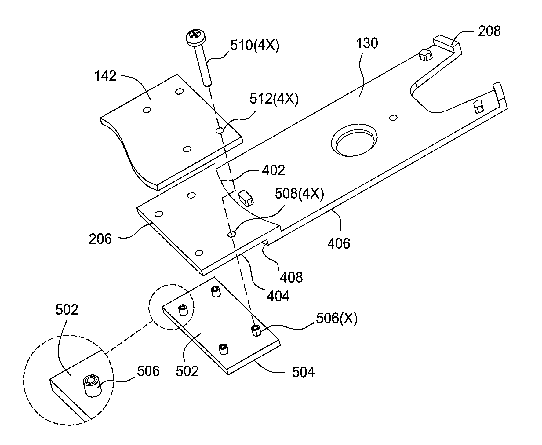
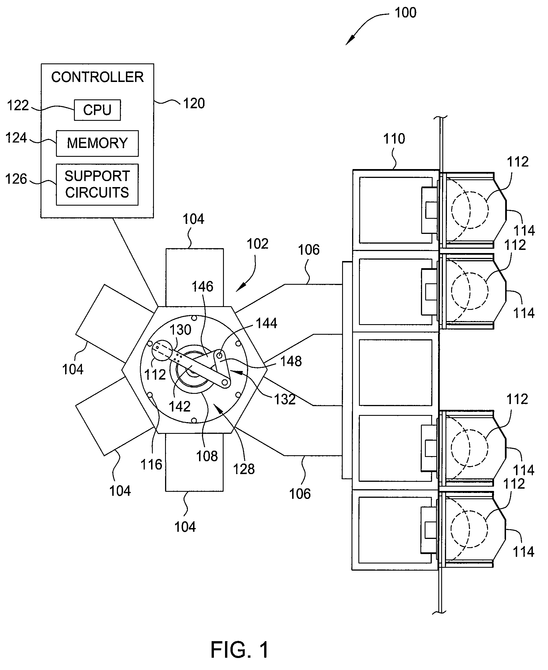
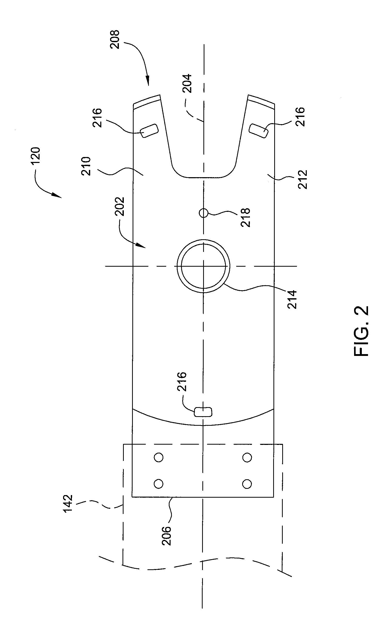
[0022]FIG. 1 depicts one embodiment of a semiconductor processing system 100 having a robot 108 equipped with an end effector or blade 130. The exemplary processing system 100 generally includes a transfer chamber 102 circumscribed by one or more process chambers 104, a factory interface 110 and one or more load lock chambers 106. The load lock chambers 106 are generally disposed between the transfer chamber 102 and the factory interface 110 to facilitate substrate transfer between a vacuum environment maintained in the transfer chamber 102 and a substantially ambient environment maintained in the factory interface 110. One example of a processing system which may be adapted to benefit from the invention is a CENTURA® processing platform available from Applied Materials, Inc., of Santa Clara, Calif. It is contemplated that the blade 130 may be utilized on other robots and processing systems, including those available from other manufacturers.

[0023]The factory interface 110 generally...


PUM


Abstract

A robotic end effector or blade suitable for transferring a substrate in a processing system is provided. In some embodiments, an end effector can include a body having opposing mounting and distal end, the body fabricated from a single mass of ceramic. The body can include a pair of arcuate lips extending upward from an upper surface of the body. Each lip is disposed on a respective finger disposed at the distal end of the body. An arcuate inner wall extends upward from the upper surface at the mounting end of the body. The inner wall and lips define a substrate receiving pocket. A plurality of contact pads extend upward from the upper surface of the body for supporting the substrate thereon. A recess is formed in a bottom surface of the body to accommodate a mounting clamp.

Description

CROSS-REFERENCE TO RELATED APPLICATION[0001]This application claims benefit to U.S. Provisional Patent Application No. 60 / 884,542, filed Jan. 11, 2007 (APPM / 11788L), which is incorporated by reference in its entirety.BACKGROUND OF THE INVENTION[0002]1. Field of the Invention[0003]The embodiments of the invention generally relate to robot components utilized in high temperature semiconductor processing systems.[0004]2. Background of the Related Art[0005]Semiconductor substrate processing is typically performed by subjecting a substrate to a plurality of sequential processes to create devices, conductors and insulators on the substrate. These processes are generally performed in a process chamber configured to perform a single step of the production process. In order to efficiently complete the entire sequence of processing steps, a number of process chambers are typically coupled to a central transfer chamber that houses a robot to facilitate transfer of the substrate between the sur...

Claims


Application Information

Patent Timeline
Patent Type & Authority Patents(United States)
IPC IPC(8): B65G49/07
CPCH01L21/67742H01L21/68707Y10S414/135Y10S414/141B25J11/0095B25J15/0019
Inventor NG, ERIC
Owner APPLIED MATERIALS INC
Learn More