Transmission device, reception device and radio communication method

a technology of receiving device and transmitter, applied in the field of transmitter, receiving device, radio communication method, can solve the problems of degrading accuracy and wide frequency band used, and achieve the effect of not degrading reception quality

Active Publication Date: 2010-05-25
INTERDIGITAL PATENT HLDG INC
View PDF21 Cites 12 Cited by
  • Summary
  • Abstract
  • Description
  • Claims
  • Application Information

AI Technical Summary

Benefits of technology

[0005]It is an object of the present invention to provide a transmitting apparatus, receiving apparatus, and radio communication method whereby a greater amount of data is transmitted without degrading reception quality using a limited frequency band.

Problems solved by technology

However, a drawback in this case is that the frequency band used becomes wider.
There is also a drawback in that, since a different frequency band from that for data is used, unique words and pilot symbols undergo different propagation path fluctuations than data, and precision when compensating for channel fluctuations degrades.

Method used


Image

  • Transmission device, reception device and radio communication method
  • Transmission device, reception device and radio communication method
  • Transmission device, reception device and radio communication method

Examples


embodiment 1

[0088]In Embodiment 1, a case is described in which a modulated signal in which information is digitally modulated (hereinafter referred to as “information modulated signal”) and a modulated signal in which a specific signal sequence is digitally modulated (hereinafter referred to as “specific information signal”) are multiplexed in the same frequency band on the transmitting side, and on the receiving side the multiplexed signals are separated and the information modulated signal is demodulated.

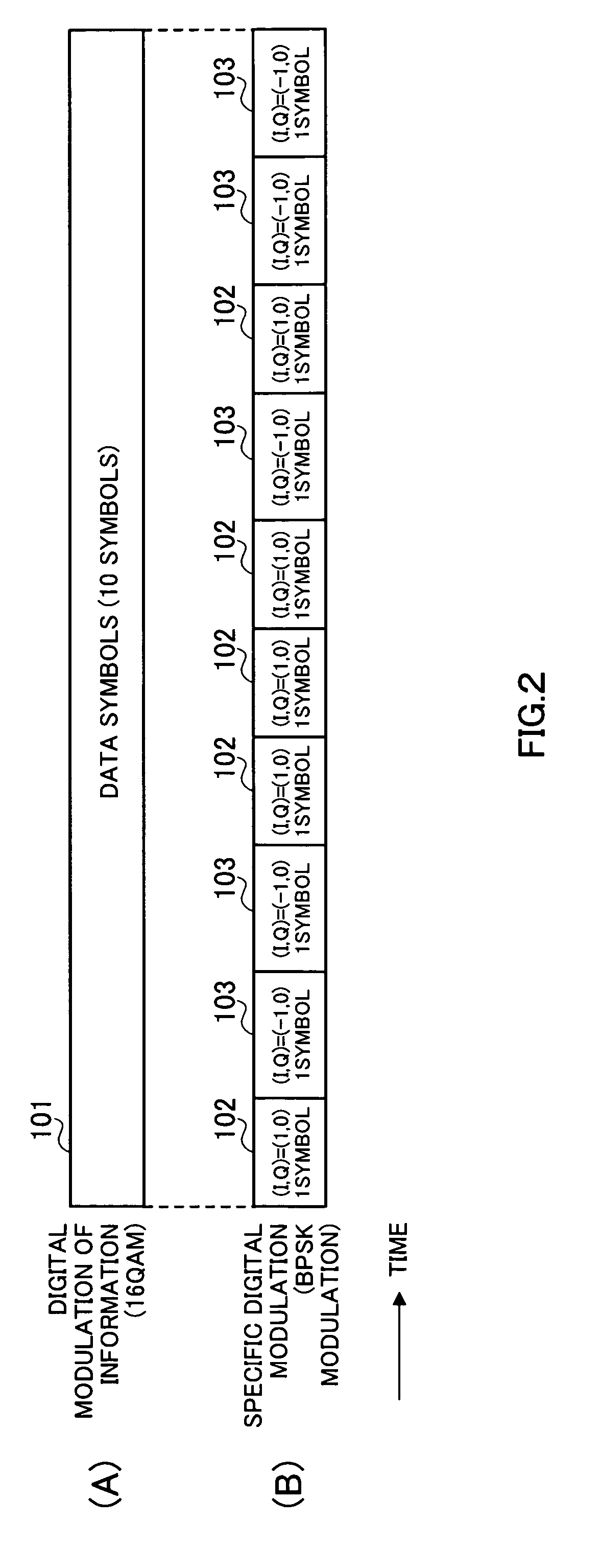
[0089]FIG. 2 is a drawing showing an example of frame configurations according to Embodiment 1. FIG. 2(A) shows the information modulated signal frame configuration when 16 QAM is used as the modulation method, with data symbols 101 comprising 10 symbols. FIG. 2(B) shows the specific modulated signal frame configuration, with BPSK modulation used as the modulation method by way of example.

[0090]FIG. 3 is a drawing shows 16 QAM signal point mapping in the in-phase-quadrature plane (I-Q plane)...

embodiment 2

[0118]In Embodiment 2 a radio communication method is described whereby a transmit signal multiplexed according to Embodiment 1 is transmitted simultaneously by a plurality of stations.

[0119]FIG. 14 shows the configuration of a radio communication system according to this embodiment. In FIG. 14, a transmit signal generating station 1304 generates, and transmits to a base station 1301 and base station 1302, a modulated signal with the frame configuration in FIG. 2, for example, and base station 1301 and base station 1302 perform radio transmission of an information modulated signal and specific modulated signal multiplexed in the same frequency band. It is assumed that a terminal 1303 is equipped with a receiving apparatus as shown in FIG. 7, and synchronization section 603 is equipped with a correlation calculation section as shown in FIG. 8.

[0120]As shown in FIG. 14, terminal 1303 receives a radio wave from base station 1301 and a radio wave from base station 1302. At this time, te...

embodiment 3

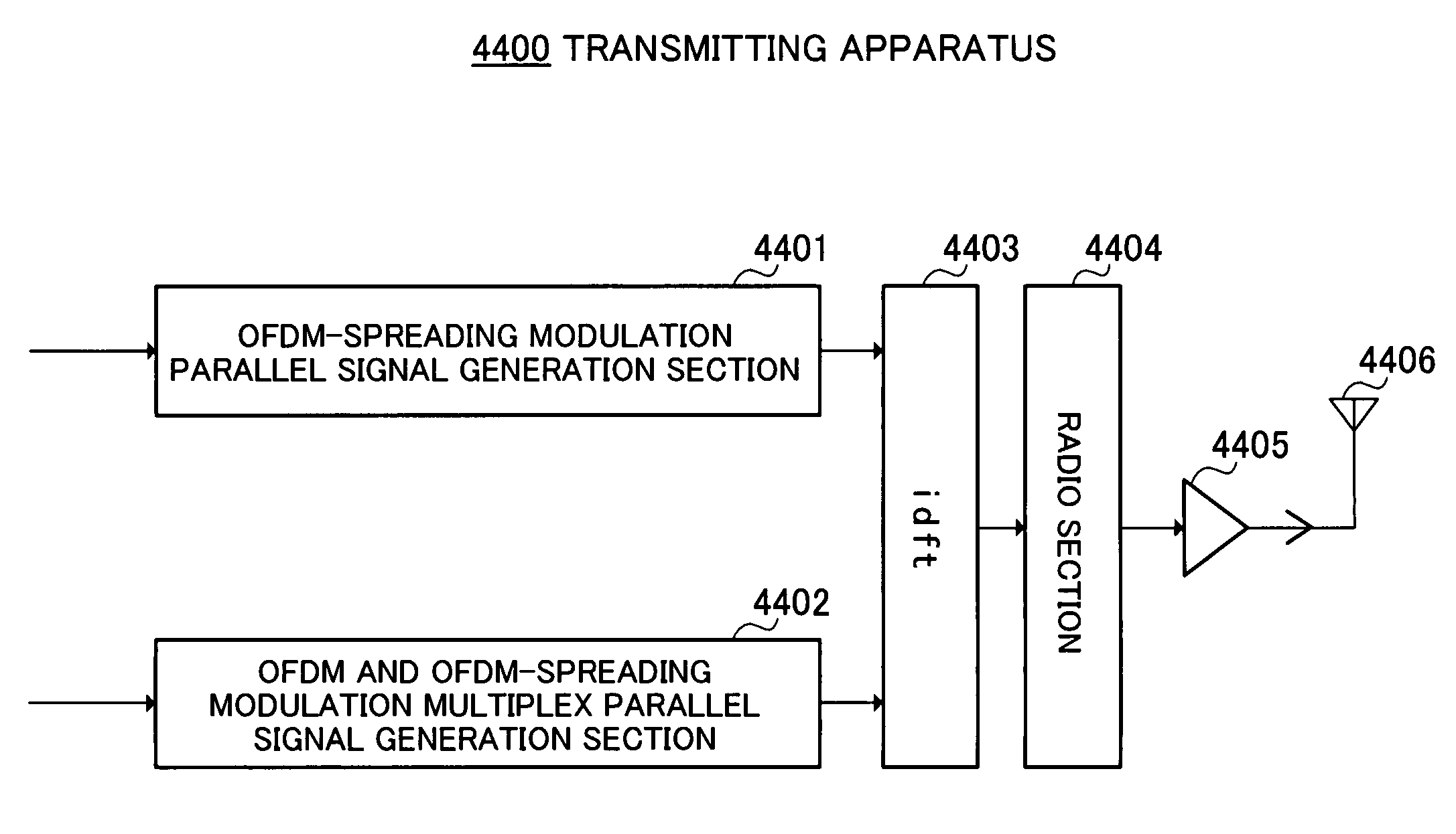
[0122]In Embodiment 3 a case is described in which an information modulated signal and a modulated signal modulated by means of a spread spectrum communication system modulation method (hereinafter referred to as “spread modulated signal”) are multiplexed in the same frequency band, and on the receiving side the multiplexed signal is separated into an information modulated signal and spread modulated signal and demodulated.

[0123]FIG. 16 shows an example of frame configurations on the time axis of a radio communication system according to this embodiment. FIG. 16(A) shows the information modulated signal frame configuration, and assumes the use of 16 QAM modulation as the modulation method. Reference codes 1501, 1502, and 1503 indicate pilot symbol fields, each comprising one symbol. Reference codes 1504 and 1505 indicate data symbol fields, each comprising 10 symbols. FIG. 16(B), on the other hand, shows the information spread modulated signal frame configuration. Reference codes 15...


PUM


Abstract

On a transmitting side, a spread modulated signal that has undergone spread spectrum processing and an information modulated signal that has not undergone spread spectrum processing are multiplexed in a same frequency band. On the receiving side, the specific modulated signal is first demodulated by a spread spectrum demodulation section, then a replica signal of the specific modulated signal is generated by a spread spectrum modulated signal regeneration section, and the information signal that has not undergone spread spectrum processing is extracted by eliminating the replica signal from the multiplex signal. Thus, even when a large number of information signals are transmitted in a same frequency band, these signals can be separated and demodulated satisfactorily on the receiving side.

Description

TECHNICAL FIELD[0001]The present invention relates to a transmitting apparatus, receiving apparatus, and radio communication method used in a communication system in which a greater amount of data is transmitted in a limited frequency band.BACKGROUND ART[0002]An example of frame configuration along the time axis in a conventional radio communication system is shown in FIG. 1. In FIG. 1, reference code 1 indicates data symbols, reference code 2 pilot symbols, and reference code 3 a unique word. In order to demodulate a signal transmitted from a transmitting apparatus, a receiving apparatus must acquire time synchronization with the transmitting apparatus. For this purpose, the receiving apparatus acquires time synchronization by detecting unique word 3, for example. Also, when demodulating data symbols 1, the receiving apparatus compensates for channel fluctuations using pilot symbols 2.[0003]However, in a conventional radio communication system, since a unique word and pilot symbols...

Claims


Application Information

Patent Timeline
Patent Type & Authority Patents(United States)
IPC IPC(8): H04J11/00H04B1/707H04B1/7107H04L1/00H04L5/02
CPCH04B1/707H04B1/711H04J13/00H04L1/0003H04L5/0016H04L27/18H04L27/227H04L27/2602H04L27/34H04L27/38H04B1/7075H04B2201/70705H04L1/0023H04L5/0007H04L5/0048H04L27/2662H04L2027/004H04L2027/0061H04B2201/70716H04B2201/70728H04L5/0044H04L27/364
Inventor MURAKAMI, YUTAKATAKABAYASHI, SHINICHIROORIHASHI, MASAYUKIMATSUOKA, AKIHIKO
Owner INTERDIGITAL PATENT HLDG INC
Why Eureka
Try Eureka