Fireplace with front face attachment

a technology of front face and fireplace, which is applied in the direction of heating fuel, lighting and heating apparatus, applications, etc., can solve the problem of relatively inefficient heat exchange system

Inactive Publication Date: 2010-06-01
ROCO INC
View PDF12 Cites 10 Cited by
  • Summary
  • Abstract
  • Description
  • Claims
  • Application Information

AI Technical Summary

Benefits of technology

[0013]It is one object of the invention to provide a fireplace which allows a single construction to be used for both louver and non-louver constructions.
[0036]Preferably the attachment includes a cover plate extending rearwardly of the top edge of the first cover panel for partly covering the first opening to allow passage of air while reducing direct vision therethrough.

Problems solved by technology

Firstly the heat exchange system is relatively inefficient since it extracts heat from only underneath the combustion chamber.
Secondly this construction is entirely different from the conventional fireplace in that it constitutes an alternative model of fireplace different from the conventional louver type construction.

Method used


Image

  • Fireplace with front face attachment
  • Fireplace with front face attachment
  • Fireplace with front face attachment

Examples


Embodiment Construction

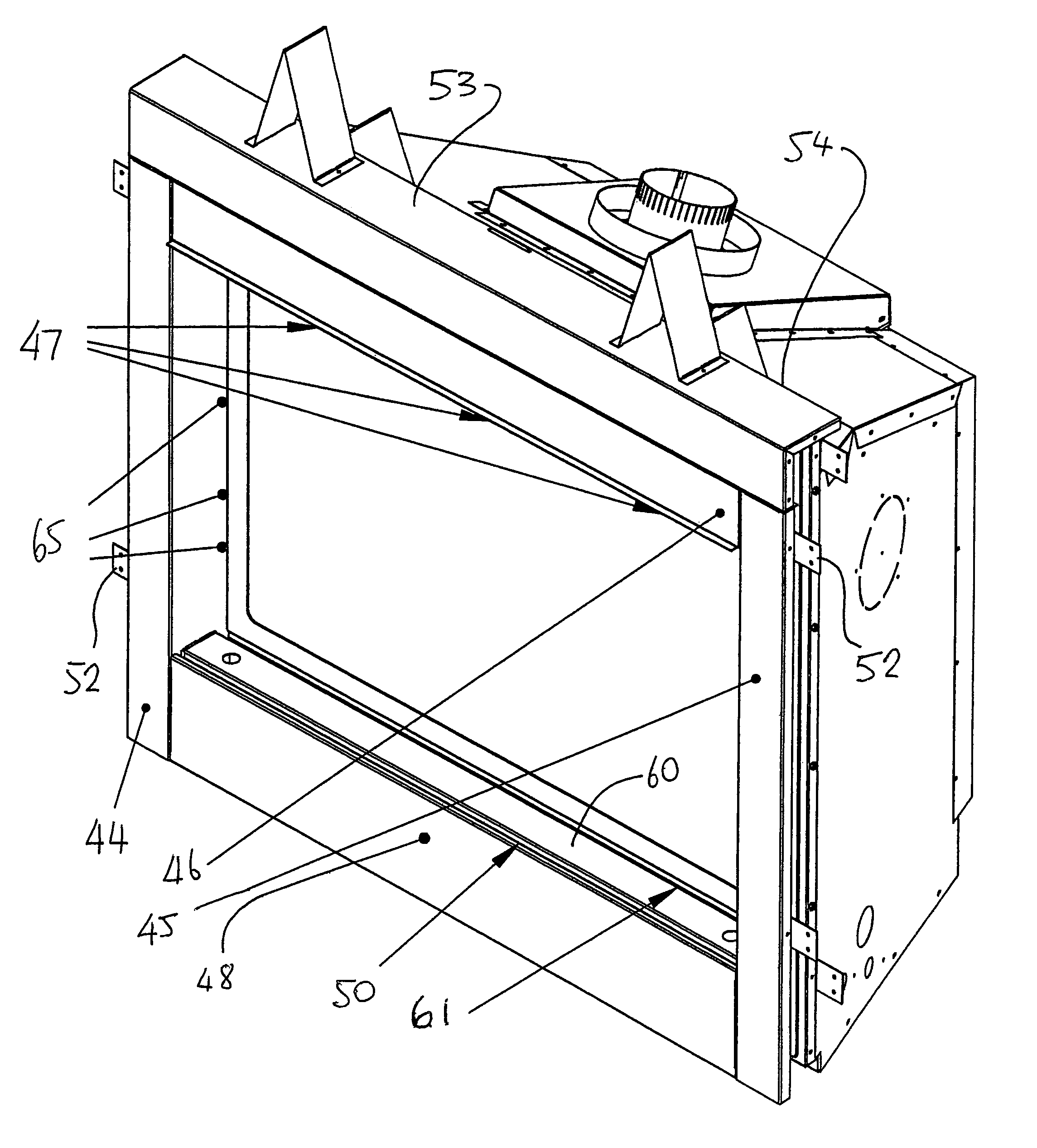
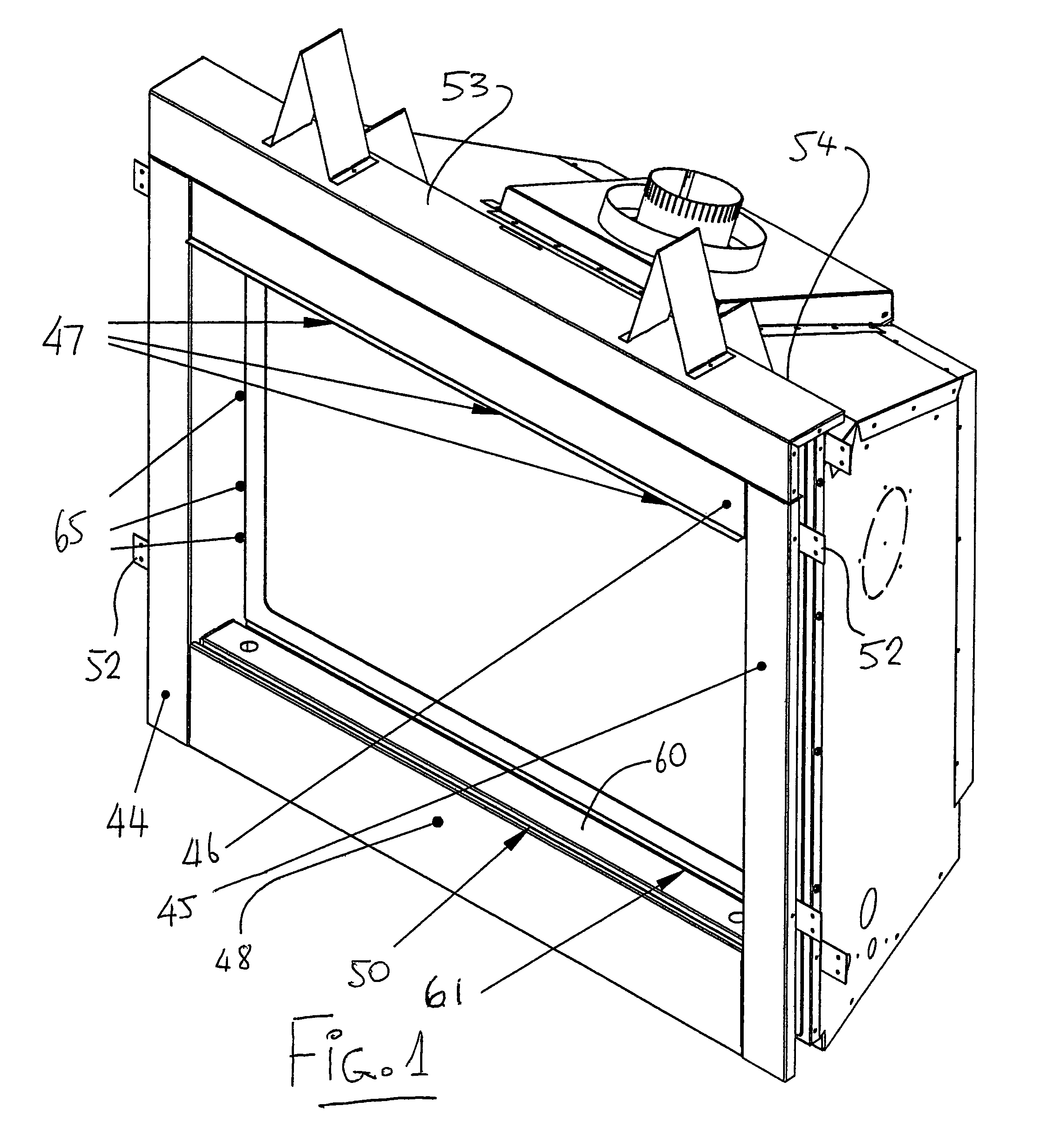
[0047]The basic fireplace assembly generally indicated at 10 includes an interior combustion chamber 11 and an exterior housing 12. These are generally of conventional construction well known to one skilled in the art and further details of fireplaces of this general type are shown in prior U.S. Pat. No. 5,398,669 issued Mar. 21, 1995; U.S. Pat. No. 5,399,084 issued Mar. 21, 1995; U.S. Pat. No. 5,915,375 issued Jun. 29, 1999 and U.S. Pat. No. 6,050,375 issued Apr. 18, 2000 all of the present inventor, the disclosures of which are incorporated herein by reference.

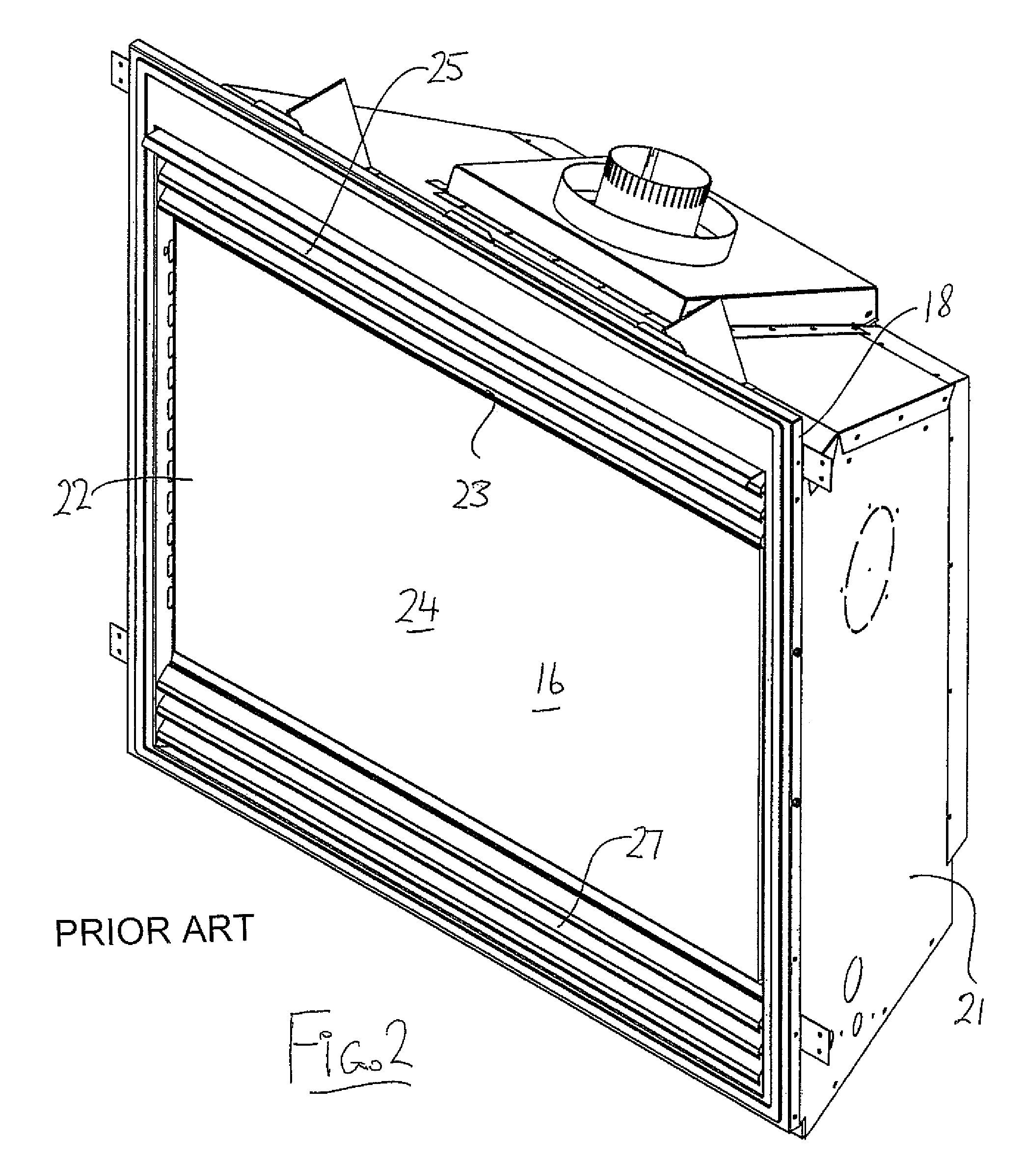
[0048]The combustion chamber 11 includes a top wall 12, a bottom wall 13, a rear wall 14 and two side walls 15. These define an open front 16 at which is located a transparent front cover which allows the occupants of the room in which the fireplace is located to view the combustion chamber and the burning materials mounted on a combustion assembly 17 again of conventional type. In the arrangement shown the glass or transpar...


PUM


Abstract

A front face attachment for a fireplace allows a single fireplace construction to be converted from a first arrangement having front facing top outlet and bottom inlet with covering louver panels for air flow around the combustion chamber to a second arrangement in which there are no front facing outlets and the top and bottom outlets are behind front cover flanges for receiving cladding materials.

Description

[0001]This invention relates to a fireplace with a front face attachment kit which allows the conversion of the fireplace from a type having front louvers for inlet and discharge openings for circulating air which are visible in front elevation to a type where the inlet and discharge openings are not visible in front elevation.BACKGROUND OF THE INVENTION[0002]Conventional gas fires of the zero-clearance type include an internal combustion chamber where the gas is burned in a combustion assembly which includes elements simulating burning materials to provide an attractive appearance. The combustion chamber includes side walls, top wall, bottom wall and a rear wall.[0003]The combustion chamber is mounted within a housing which separates the combustion chamber from exterior building components so that the housing defines a top wall, a rear wall, a bottom and sides which support the combustion chamber and define heat exchange spaces for the passage of air to maintain the exterior housin...

Claims


Application Information

Patent Timeline
Patent Type & Authority Patents(United States)
IPC IPC(8): F24B1/18F24B1/192F24B1/189F24B1/195F24B1/198F24B1/199
CPCF24B1/1808
Inventor REYHER, RUSSELL E.
Owner ROCO INC
Why Eureka
Try Eureka