Enveloping needle stick protection device

a protection device and needle technology, applied in the direction of intravenous devices, medical syringes, infusion needles, etc., can solve the problems of doctors and other medical practitioners being stuck with these used needles

Active Publication Date: 2010-06-01
MILLER MEDICAL LLC
View PDF13 Cites 23 Cited by
  • Summary
  • Abstract
  • Description
  • Claims
  • Application Information

AI Technical Summary

Benefits of technology

[0008]It is also an object of the present invention to provide a needle stick protection device wherein the spring biased lock arm includes a living hinge portion adjacent its free end creating a flexible tip at the free end of the spring biased lock arm which permits flexion of the tip about the living hinge portion in a manner allowing the detent to move from the first side of the spring biased lock arm to the second side of the spring biased lock arm.
[0011]It is another object of the present invention to provide a needle stick protection device wherein the second parallel surface prevents the tip from bending in a manner permitting the detent to move from the second side of the spring biased lock arm to the first side of the spring biased lock arm.
[0014]It is yet another object of the present invention to provide a needle stick protection device wherein the second housing member further includes a slide actuating portion secured to the first detent of the second housing member facilitating controlled movement of the second housing member relative to the first housing member.

Problems solved by technology

However, these used needles may be passed between physicians and other medical practitioners several times during the procedure.
As such, a possibility exists that physicians and other medical practitioners may be stuck with these used needles during the procedure.

Method used


Image

  • Enveloping needle stick protection device
  • Enveloping needle stick protection device
  • Enveloping needle stick protection device

Examples


Embodiment Construction

[0032]The detailed embodiment of the present invention is disclosed herein. It should be understood, however, that the disclosed embodiment is merely exemplary of the invention, which may be embodied in various forms. Therefore, the details disclosed herein are not to be interpreted as limiting, but merely as the basis for the claims and as a basis for teaching one skilled in the art how to make and / or use the invention.

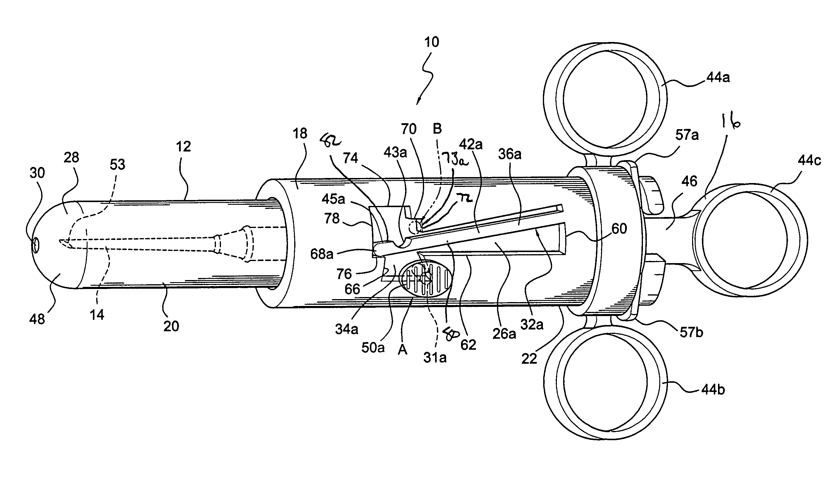
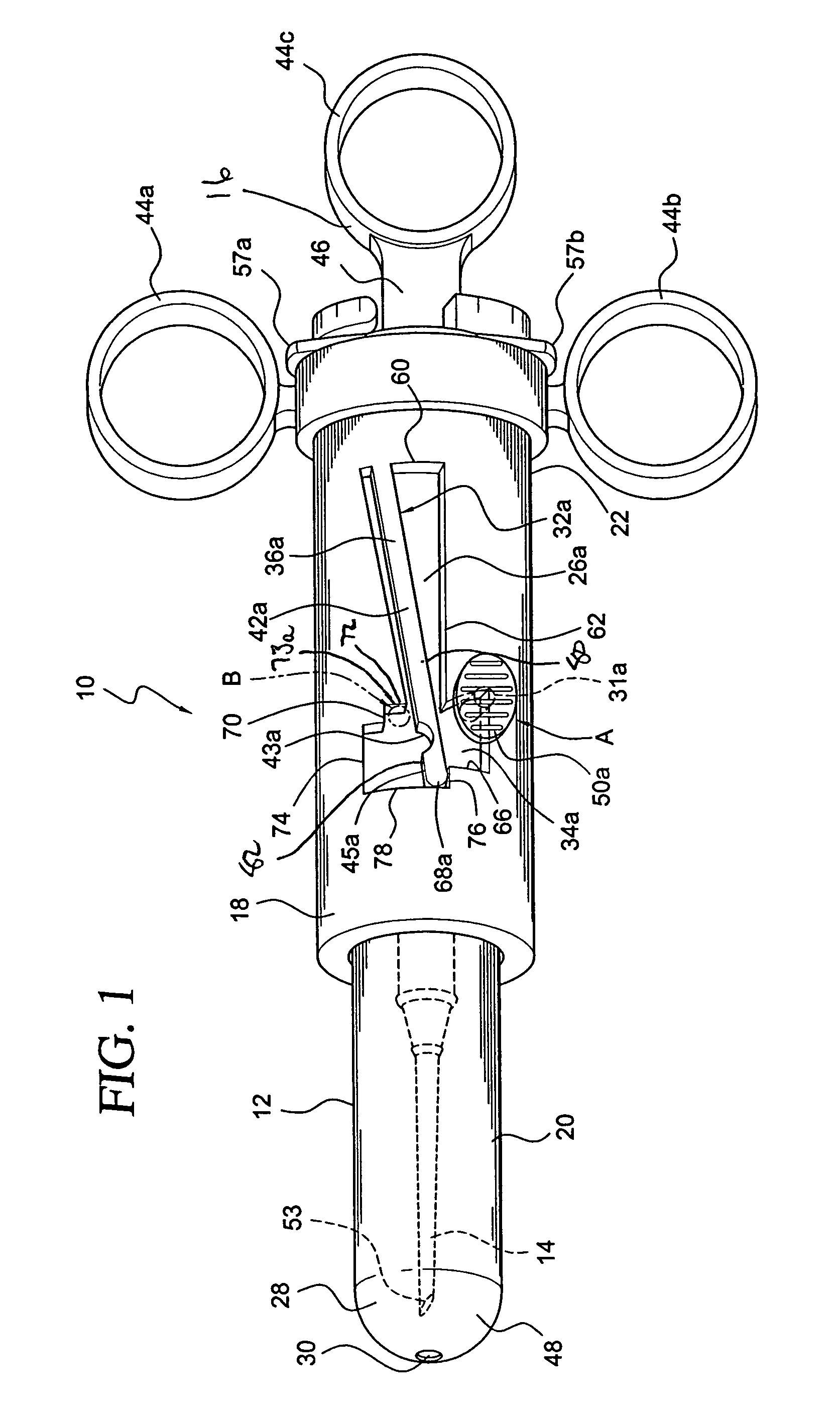
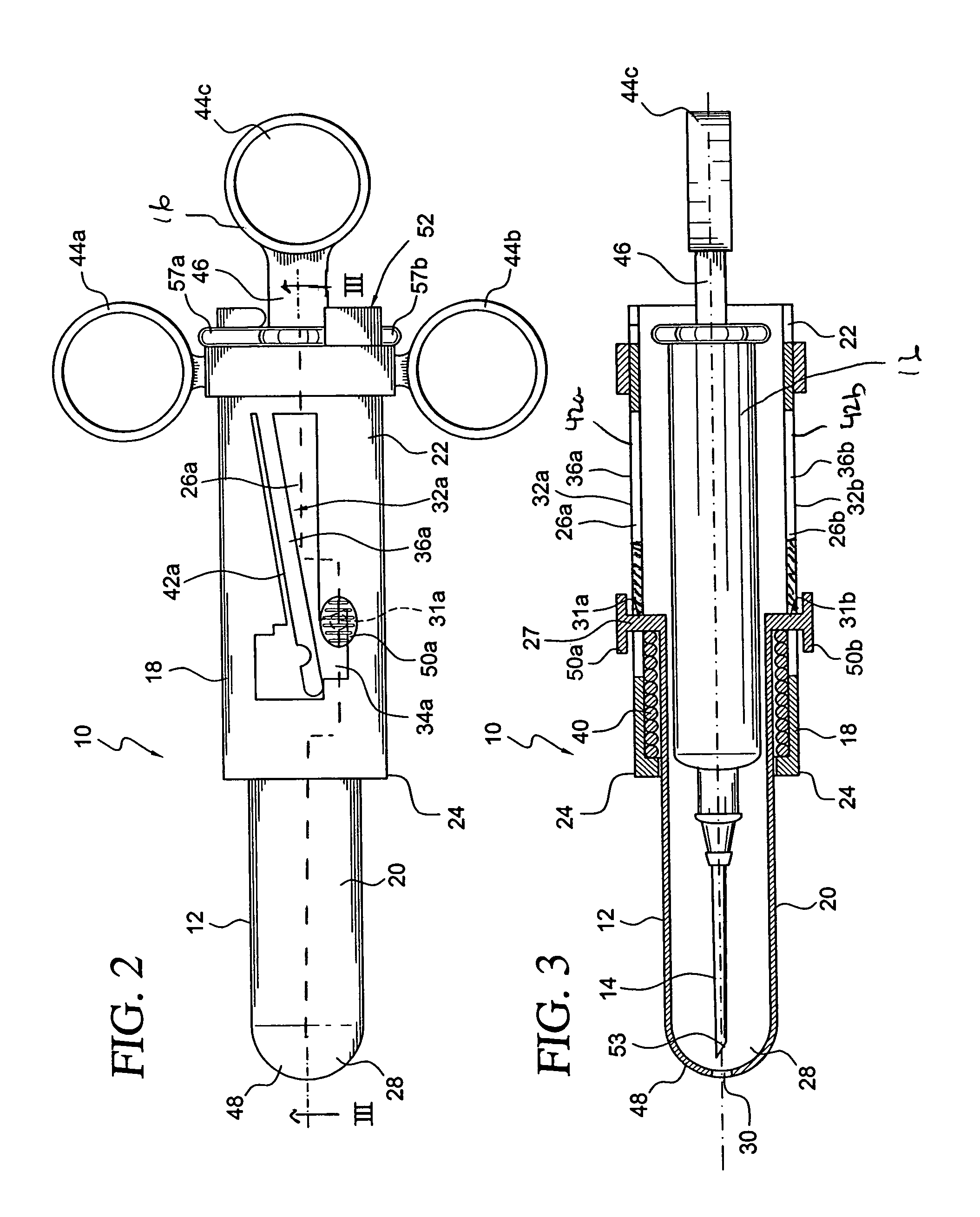
[0033]With reference to the various figures, a needle stick protection device 10 is disclosed. The needle stick protection device 10 includes a housing 12 shaped and dimensioned for positioning about a needle 14 and an associated syringe 16. The housing 12 includes a first housing member 18 telescopically coupled to a second housing member 20. The first housing member 18 includes an open first end 22 and an open second end 24. The first housing member 18 further includes slots 26a, 26b extending longitudinally along the length of the first housing member 18 along opp...


PUM


Abstract

It is, therefore, an object of the present invention to provide a needle stick protection device. The device includes a housing shaped and dimensioned for positioning about a syringe with an attached needle. The housing includes a first housing member telescopically coupled to a second housing member. A locking member is associated with a first slot of the first housing member for selectively engaging a first detent to control positioning of the second housing member relative to the first housing member. The locking member includes a first lateral retaining recess formed within the first slot for seating of the first detent when the second housing member is in its forward most position, the first lateral retaining recess being circumferentially located along a side of the first slot. The needle may be selectively covered and uncovered by selective alignment of the first detent with the slot in manner permitting controlled motion of the first housing member relative to the second housing member. The locking member further includes a lateral locking recess formed along the slot and adjacent a second side of the spring biased lock arm opposite the first side of the spring biased lock arm, wherein the needle is permanently covered when the detent is positioned within the lateral locking recess.

Description

BACKGROUND OF THE INVENTION[0001]1. Field of the Invention[0002]The invention relates to a device for preventing needle sticks. More particularly, the invention relates to a device for preventing needle sticks wherein the needle is selectively locked and released relative to a shielding device, and may ultimately be permanently locked once it is ready for disposal.[0003]2. Description of the Prior Art[0004]As those within the medical field have developed an understanding that a variety of diseases may be transferred via unclean and previously used needles, many devices have been developed for protecting medical practitioners and other individuals from previously used needles. Many currently available needle stick protection devices operate by either withdrawing the used needle into a hard protective shell or extending a hard protective shell over the used needle. These devices are generally utilized once and are then discarded in an approved collection device.[0005]While most proced...

Claims


Application Information

Patent Timeline
Patent Type & Authority Patents(United States)
IPC IPC(8): A61M5/00A61M5/32
CPCA61M5/3257A61M2005/3267A61M2005/3139A61M5/3272
Inventor MILLER, STUART H.
Owner MILLER MEDICAL LLC
Why Eureka
Try Eureka