Autofocus for minimum entropy through multi-dimensional optimization

a multi-dimensional optimization and autofocus technology, applied in the field of data processing system, can solve the problems of residual phase error, degrade the image quality, and smeared cross of synthetic aperture radar images, and achieve the effect of reducing the entropy value and minimizing the entropy value generated

Active Publication Date: 2010-06-01
THE BOEING CO
View PDF8 Cites 18 Cited by
  • Summary
  • Abstract
  • Description
  • Claims
  • Application Information

AI Technical Summary

Benefits of technology

[0016]In yet another advantageous embodiment, an apparatus comprises a computer, an objective function located in the computer, and an optimization process located in the computer. The objective function is capable of generating a phase correction with a polynomial representing a phase error, applying the phase correction to radar data, creating an image from the radar data, and calculating an entropy value from the image. The optimization process is capable of generating an array of coefficients for the polynomial that reduces the entropy value.

Problems solved by technology

Synthetic aperture radar images may be smeared in the cross range direction due to residual phase error.
This residual phase error may be caused by incomplete motion compensation, atmospheric effects, or some other source.
Phase error may be introduced by navigation errors or other sources that may degrade the quality of the image.
These techniques, however, may be limited in performance or applicable situations.
The performance of these types of techniques may be affected by the contents in the scene in which the image is made.
These types of methods are limited in the order of phase error that may be estimated.
However, with these techniques, distinguishing targets closely located in the azimuth from isolated targets cannot be perfect and using non-isolated targets may result in estimation error.
Another situation in which these techniques have difficulty is when the phase error varies spatially.
As a result, the chances of having good isolated targets in a small image block are low.
This type of situation may result in performance degradation.
Further, inaccurate local phase error estimation also poses a problem in achieving phase continuity that is desired between divided small image blocks.

Method used


Image

  • Autofocus for minimum entropy through multi-dimensional optimization
  • Autofocus for minimum entropy through multi-dimensional optimization
  • Autofocus for minimum entropy through multi-dimensional optimization

Examples


Embodiment Construction

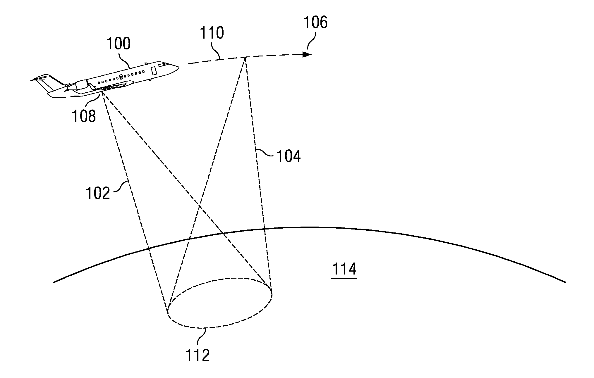
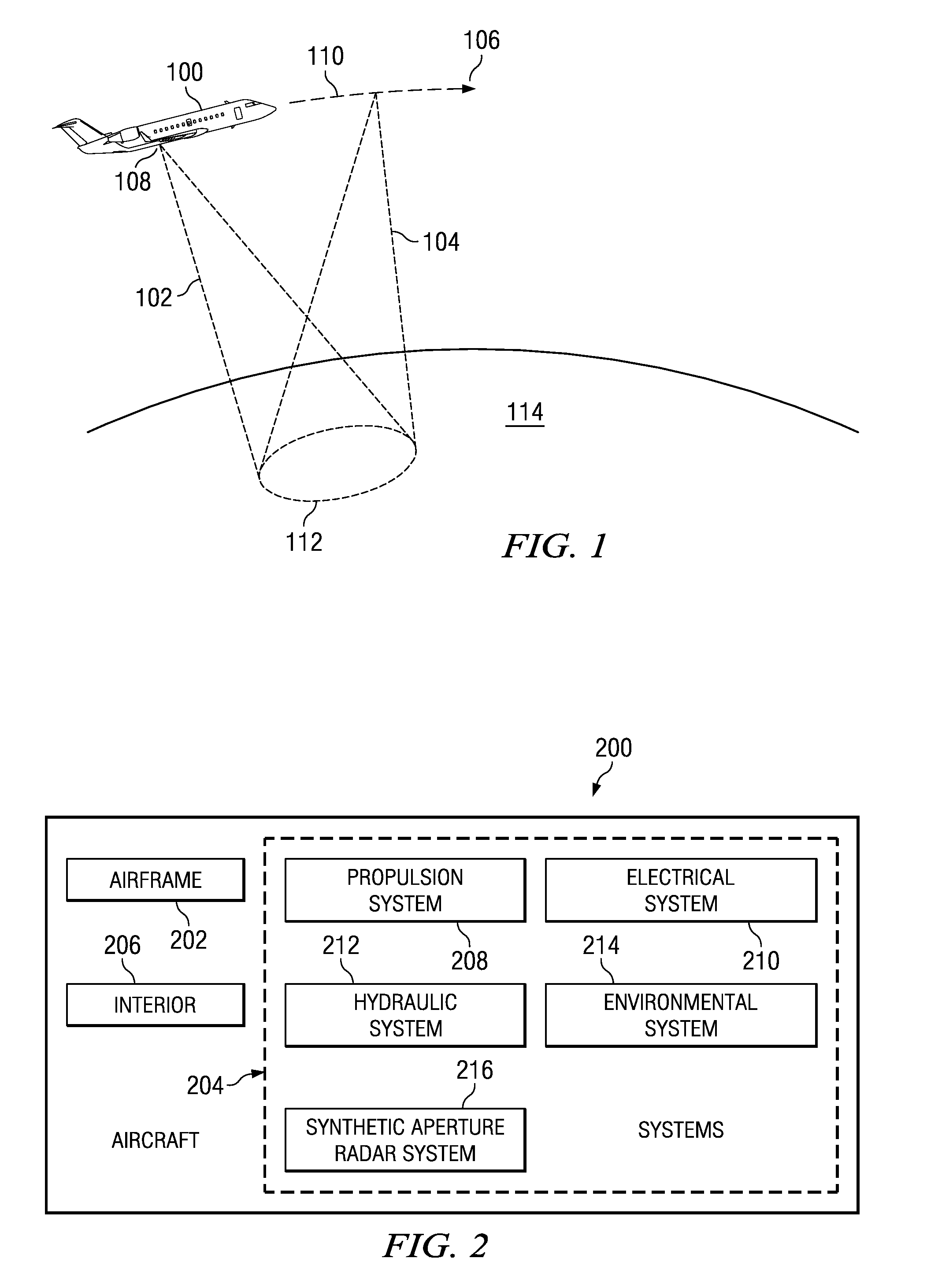
[0028]With reference now to the figures and in particular with reference to FIG. 1, a diagram illustrating the collection of data by a synthetic aperture radar system for the case of spotlight mode is depicted in accordance with an advantageous embodiment. In this example, aircraft 100 may include a synthetic aperture radar system, which may generate an array of pulses such as, for example, pulses 102 and 104 while aircraft 100 travels along the direction of dotted line 106. The different dots in dotted line 106 may represent sampling points.

[0029]For example, pulse 102 is generated at dot 108, while pulse 104 is generated at dot 110. In these examples, pulses 102 and 104 are radio frequency pulses that illuminate or target section 112 on ground 114. Aircraft 100 receives return or response signals from pulses 102 and 104. These responses form radar data. These responses may be recorded as amplitude and phase to form the radar data. In other words, the radar data may take the form o...


PUM


Abstract

A computer implemented method, apparatus, and computer usable program code for focusing an image. In one advantageous embodiment, a method is used to focus an image. Optimization is performed to identify an array of coefficients for a polynomial representing a phase correction in a manner that minimizes an entropy value generated by an entropy calculation for the image. The array of coefficients is applied to the polynomial to obtain a desired phase correction. A phase error in the image is corrected using the desired phase correction to focus the image.

Description

BACKGROUND INFORMATION[0001]1. Field[0002]The present disclosure relates generally to an improved data processing system and in particular to a method and apparatus for processing image data. Still more particularly, the present disclosure relates to a method, apparatus, and computer usable program code for focusing an image using data generated by a synthetic aperture radar.[0003]2. Background[0004]Synthetic aperture radar (SAR) is a form of radar in which a beam is generated that may be used for applications such as, for example, remote sensing and mapping. In one application, a radar antenna may be attached to an aircraft. A single pulse or signal may be radiated from the antenna that may have different dimensions in the horizontal and vertical direction to achieve desired beam width. Often times, the signal radiated from the antenna may illuminate the terrain below the aircraft outwards towards the horizon. The amplitude and phase of the signal returning from a given location on...

Claims


Application Information

Patent Timeline
Patent Type & Authority Patents(United States)
IPC IPC(8): G01S13/00
CPCG01S13/9035G01S13/904G01S13/9019G01S13/9017
Inventor CHO, KWANG M.
Owner THE BOEING CO
Why Eureka
Try Eureka