
Shell for external components of hearing aid systems

Inactive Publication Date: 2010-06-01
ADVNACED BIONICS LLC
View PDF10 Cites 32 Cited by
  • Summary
  • Abstract
  • Description
  • Claims
  • Application Information

AI Technical Summary

Benefits of technology

[0005]The present invention addresses the above and other needs by providing a protective, interchangeable shell capable of covering a variety of separate hearing system components. The shell serves to both enhance the aesthetic appearance and protect the delicate nature of each hearing system component, thereby permitting each hearing system user to modify the user's hearing components to meet the demands of the user's unique lifestyle.
[0006]The shell adds protection. Because the shell is attached to the outer surface of the plastic component covering, it is unnecessary to remove the plastic component covering and expose delicate and expensive electronic circuitry to damage in order to change the overall color or appearance of the component. Further, an embodiment of the shell covers and protects controls that can be inadvertently changed by younger users or by active users during aggressive activity where there is no protective covering or shell on the component. The protective shell also shields the valuable component upon impact if the component falls off the user or is hit or jostled during activity. Often, hearing system users sweat during physical activity or otherwise expose their components to moisture. The protective shell serves as an added barrier that absorbs moisture or prevents moisture from penetrating the components' original casings and damaging electronic circuitry that is encased within the component's original casings.
[0007]The shell provides convenient interchangeability. The shell is conveniently and interchangeably attached to the outer surface of a Behind-the-Ear (BTE) processor, a hearing aid, a headpiece, or other hearing system component through a variety of different magnetic or mechanical attachment means, such as a simple clip-on or snap-on arrangement.
[0008]The shell improves appearance. In one embodiment, the shell is made of a disposable material so that by replacing shells, the component can maintain an overall clean and new appearance. Further, a variety of different shapes, sizes, and color schemes may be applied to the shell in a manner that makes the hearing systems more aesthetically pleasing.
[0009]The shell adds stability. The shell includes additional structure that extends around the ear or other body part to which the component attaches in order to increase the component's ability to adhere to the body. The shell can also include materials with unique characteristics that increase the shell's adherence to a user's body. This additional structure or unique material secures the component to the user better than the component could be secured alone and thus protects the component from falling off the body of a user or from unwanted movement or jostling of the component.
[0010]All of the above mentioned and other benefits of the present invention permit a hearing system user to live life unfettered by concerns of protection, usability, and appearance that previously limited the user's freedom and hampered the user's unique lifestyle.

Problems solved by technology

Because the shell is attached to the outer surface of the plastic component covering, it is unnecessary to remove the plastic component covering and expose delicate and expensive electronic circuitry to damage in order to change the overall color or appearance of the component.
Often, hearing system users sweat during physical activity or otherwise expose their components to moisture.

Method used


Image

  • Shell for external components of hearing aid systems
  • Shell for external components of hearing aid systems
  • Shell for external components of hearing aid systems

Examples


second embodiment

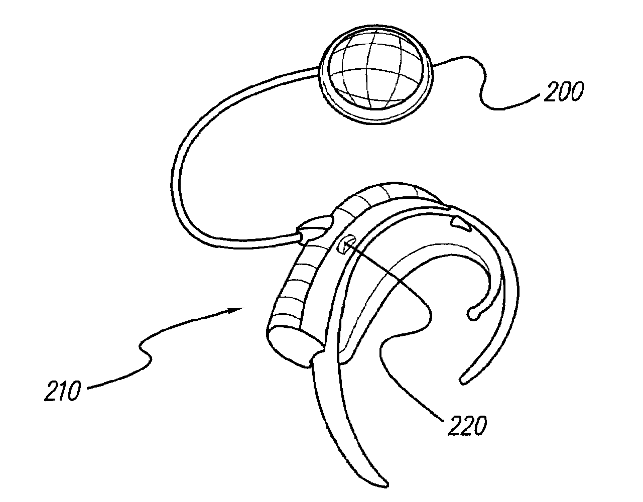
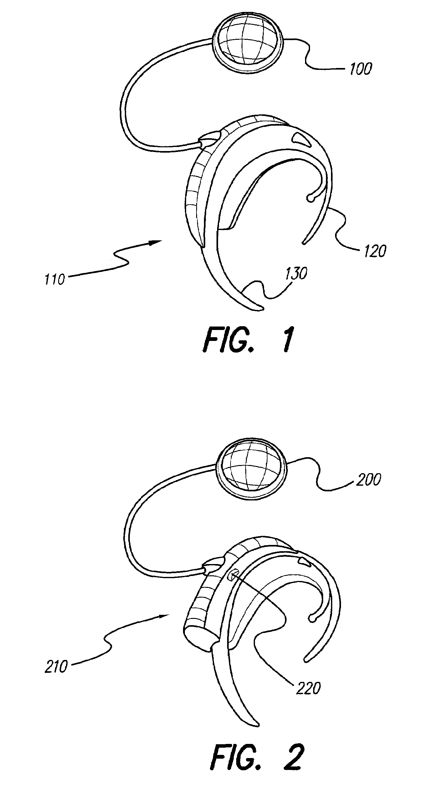
[0048]FIG. 2 is a front view of a shell system wherein a headpiece shell 200 may be attached to a headpiece and a shell 210 may be attached to a BTE Unit. Shell 210 includes a control wheel 220 that corresponds with a volume or other control of the BTE Unit, thus allowing a user to control the volume or other parameter of the BTE Unit with the shell 210 attached to the BTE Unit.

third embodiment

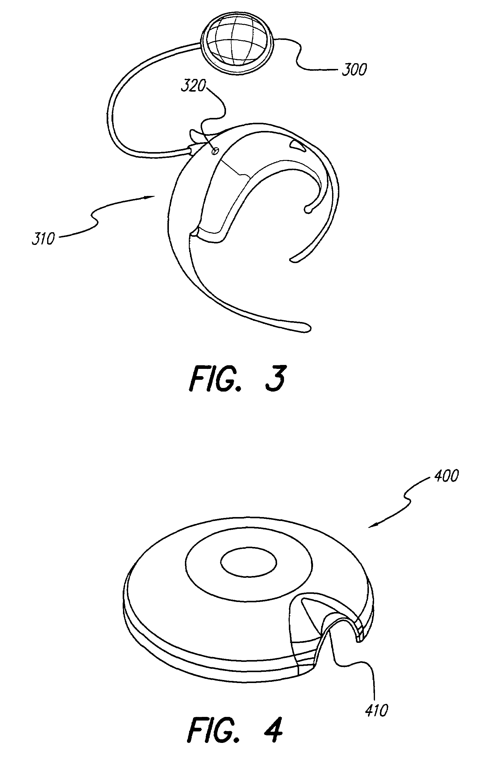
[0049]FIG. 3 is a front view of a shell system wherein a headpiece shell 300 may be attached to a headpiece and a shell 310 may be attached to a BTE Unit. Shell 310 includes an opening 320 that permits a user to access a control wheel or button on the BTE Unit, thus permitting the user to control at least one function of the BTE Unit with the shell 310 attached to the BTE Unit.

[0050]FIG. 4 is a perspective view of a shell 400 that attaches to a headpiece. Shell 400 may be a thin and flexible plastic membrane that may be thermally formed to fit the outside of the headpiece. The edge of shell 400 defines a hole or arch 410 that fits around a cable exiting the headpiece. FIG. 4A is a top view of shell 400. FIG. 4B is a cross-sectional view of shell 400 taken along lines 4B-4B of FIG. 4A. A small and thin ferrous disk 420, preferably constructed of nickel plated steel or any other conductive metal, may be attached to the inside of shell 400. Disk 420 may be glued to the underside of she...

seventh embodiment

[0053]FIG. 7 is a front view of a shell 700 attached to a BTE Unit. The embodiment of FIG. 7 is an alternate embodiment of shell 600 (FIG. 6). All corresponding elements, advantages, and alternate embodiments of shell 600 are a part of the design of the shell 700 of FIG. 7.

[0054]FIG. 8 is a front view of a shell 800 attached to a BTE Unit. Rather than a tail portion shown in earlier figures, the body of shell 800 includes an appendage that forms a complete ring 810 that wraps around the circumference of the ear. Like the appendages described elsewhere in this disclosure, ring 810 helps stabilize the shell 800 around the ear of a user. All other corresponding elements, advantages, and alternate embodiments of shell 600 are a part of the design of shell 800.


PUM


Abstract

Detachable shells on hearing system components are used to provide protection to the hearing system components, to be visually pleasing, to provide visibility and to increase system attachment stability, among other functions. The detachable shells allow the overall shape and appearance of the components to be changed, thereby complementing a variety of activities that constitute a hearing system user's unique lifestyle.

Description

[0001]The present application claims the benefit of U.S. Provisional Patent Application Ser. No. 60 / 435,407, filed Dec. 20, 2002, which application is herein incorporated by reference in its entirety.FIELD OF THE INVENTION[0002]The present invention relates to hearing aid and cochlear implant systems and, more particularly, to coverings for the external components of such systems.BACKGROUND OF THE INVENTION[0003]Users of hearing aid and cochlear implant systems (hearing systems) have limited options to alter the appearance or function of external components for these systems. The only currently available options for altering the appearance or function of external components such as behind-the-ear sound or speech processors and headpieces are to change the color of the external components by replacing specific plastic parts of the processor or headpiece or by applying a decal to the outer surface of the processor or headpiece. Although desirable, replacing specific plastic parts is i...

Claims


Application Information

Patent Timeline
IPC IPC(8): A61N1/00
CPCH04R25/65H04R25/658
Inventor LYNCH, DOUGLAS PCRAWFORD, SCOTT A
Owner ADVNACED BIONICS LLC
Learn More