Handlebar grip for a bicycle or a motorcycle

Inactive Publication Date: 2013-05-28
LI JIN CANG
View PDF5 Cites 2 Cited by
  • Summary
  • Abstract
  • Description
  • Claims
  • Application Information

AI Technical Summary

Benefits of technology

The handlebar grip is designed to provide better softness and comfort when holding it. It includes a holding face on the first segment of the sleeve member and a limiting projection to enhance the feel of the grip. The handle also has secure retaining housings that prevent the grip from coming loose. The sleeve and the retaining housings are made of different materials, such as rubber or plastic, and engaging covers made of metal or carbon fiber, making the grip more aesthetically appealing.

Problems solved by technology

But it can not be removed easily.
However, the housing and the cover can not be replaced randomly based on requirement.
Besides, the cover can not be replaced independently, and the housing has to be retained by using the metal loop.
Nevertheless, the housings cover the handlebar so only an extending segment of the projecting portion of the body is used to be the holding surface, accordingly a size of the housings is large to cause a higher production cost and a heavy weight.
In addition, an area of the body grasped by a rider is limited.
The retaining bolts are served to fix the body on the handle, thus increasing assembly time.

Method used


Image

  • Handlebar grip for a bicycle or a motorcycle
  • Handlebar grip for a bicycle or a motorcycle
  • Handlebar grip for a bicycle or a motorcycle

Examples


first embodiment

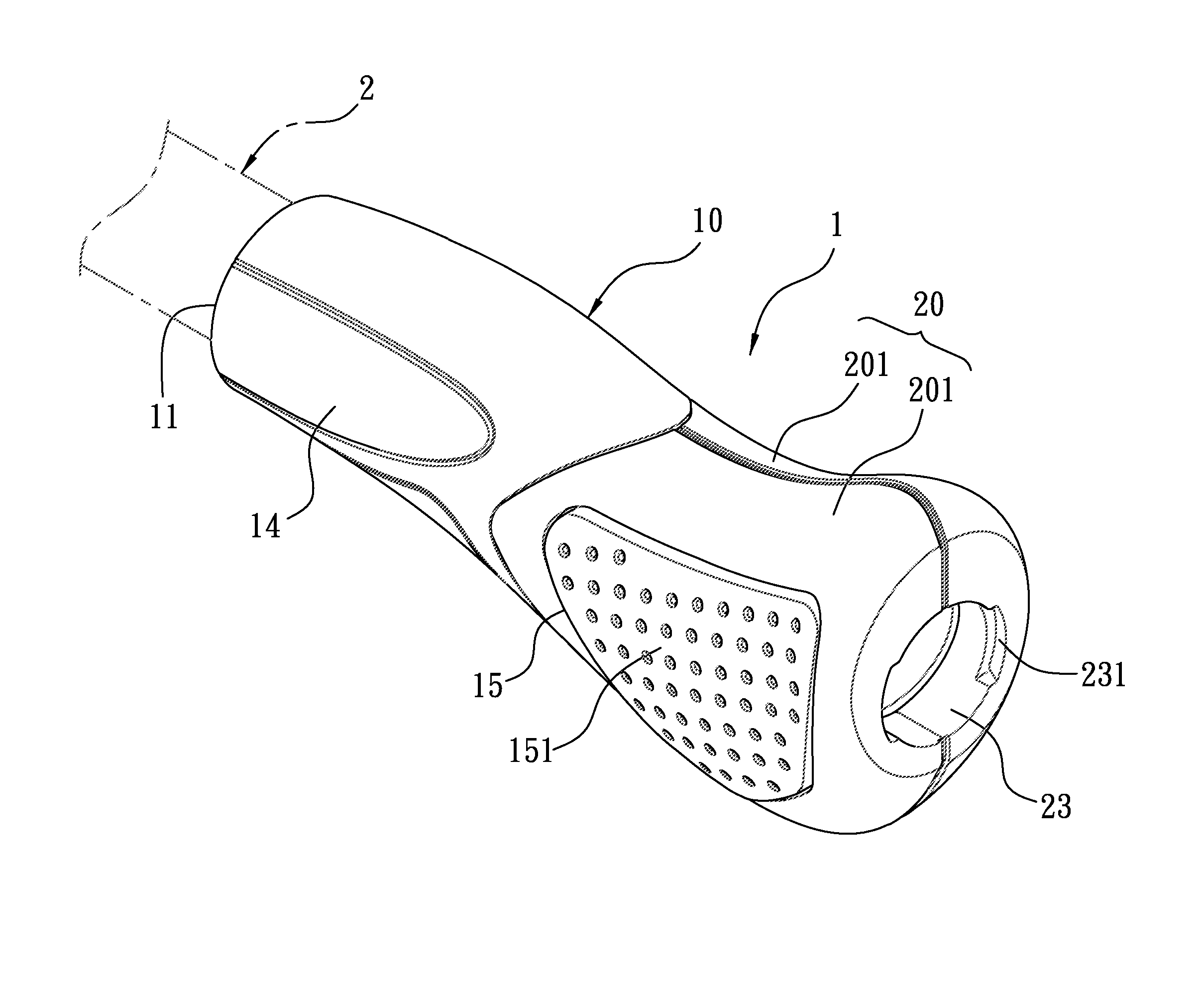
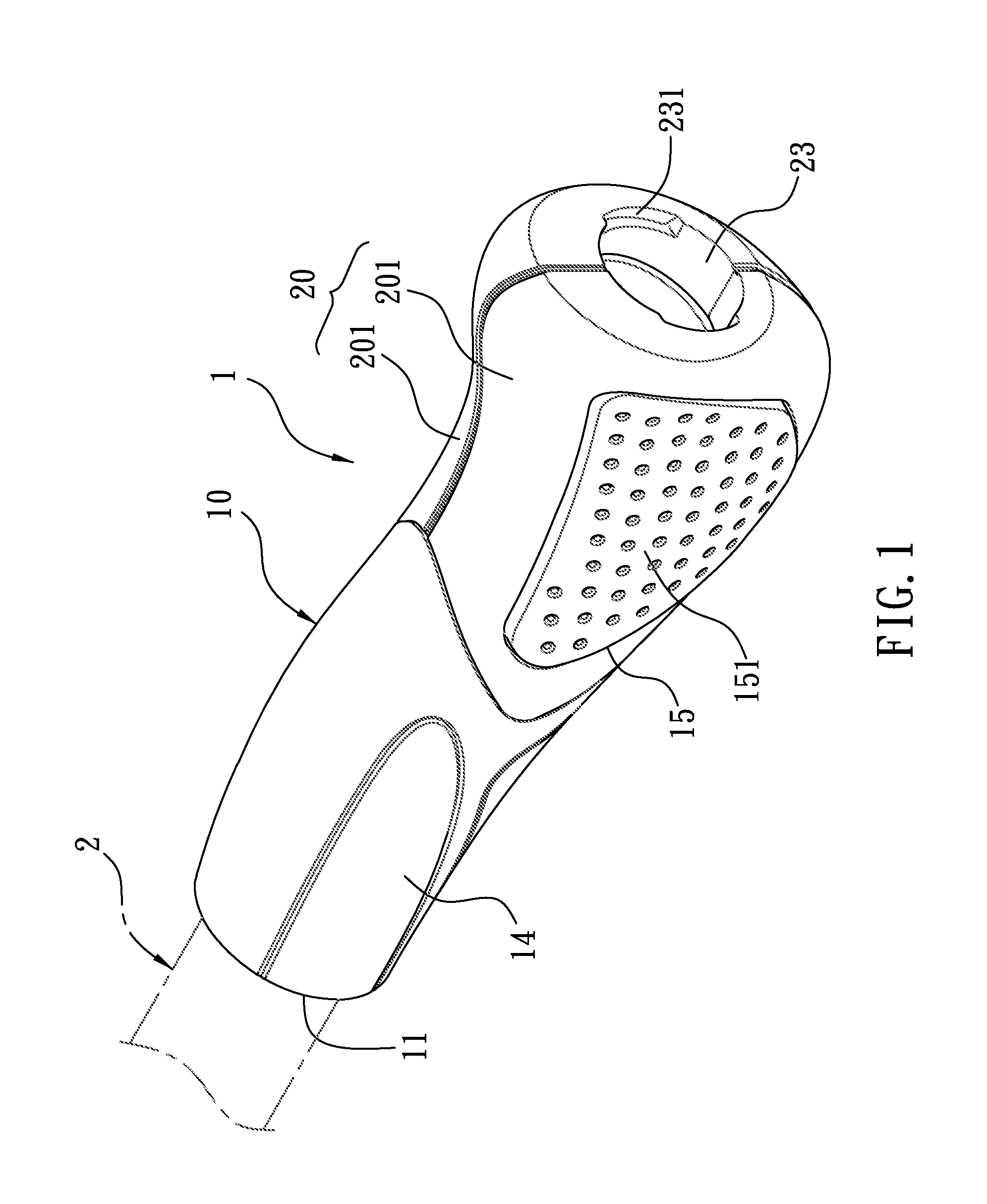
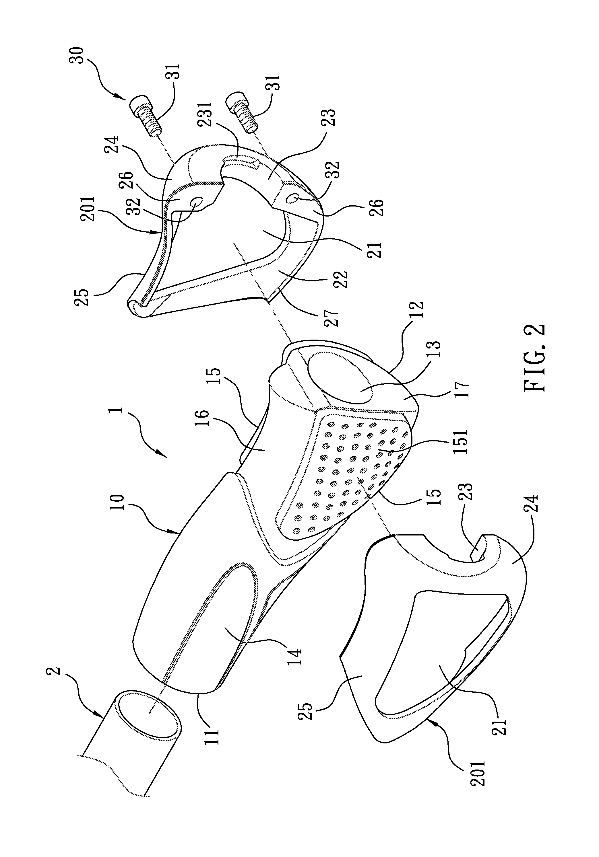
[0035]Referring to FIGS. 1 and 2, a handlebar grip 1 according to the present invention is fixed on each of two handles 2 for a bicycle or a motorcycle to be held by a rider and comprises a soft sleeve member 10, a retaining housing 20, and a locking device 30.

[0036]The sleeve member 10 is integrally formed from a rubber material or a plastic material and includes a first segment 11, a second first segment 12, and a through hole 13 between the first segment 11 and the second segment 12 to insert the handle 2, a holding face 14 formed on the first segment 11 to be held the rider, two limiting projections 15 extending outward from a palm side and a distal side of a finger section of the second segment 12 respectively, and a recessed pressing zone 16 around each of the two limiting projections 15 of the second segment 12. The palm side of the second segment 12 of the sleeve member 10 is opposite to one side of a palm of a hand of the rider, and the distal side of the finger section of ...

case 42

[0054]a receiving case 42 screwed on an inner side of the lid 41 and received in an interior of an outer end of the handle 2 and having a returning spring 421 connected with a bottom end thereof;

[0055]a cell holder 43 received in the receiving case 42 and pushed outward by the returning spring 421;

[0056]a plurality of cells 44 being a lithium cell and received in the cell holder 43;

[0057]a touch button 45 disposed on an inner end of the cell holder 43 to be pressed;

[0058]a LED light 46 fixed on an outer end of the cell holder 43 and extended out of the bore 411 of the lid 41 so that when the rider presses the LED light 46, the cell holder 43 is actuated to move inward, and then the touch button 45 contacts with an inner surface of the receiving case 42 to turn on / off light or to switch light modes, and after the rider stops pressing the LED light 46, the returning spring 42 returns back to an original position automatically.

[0059]The warning device 40 includes two hook-shaped blocks...


PUM


Abstract

A handlebar grip for a bicycle or a motorcycle contains a sleeve member including a first segment, a second first segment, and a through hole, a holding face formed on the first segment, at least one limiting projection extending outward from the second segment, and a recessed pressing zone; a retaining housing including two hard engaging covers, at least one restricting groove to extend the limiting projection outward; a wall face formed around each of the at least one restricting groove and on each of the two engaging covers; the each of the two engaging covers including a C-shaped locking face; a locking device applied to lock the two engaging covers together so that the two engaging covers are locked on the handle outside the second segment by using two C-shaped locking faces respectively, and the two limiting projections of being axially limited by the two restricting grooves respectively.

Description

BACKGROUND OF THE INVENTION[0001]1. Field of the Invention[0002]The present invention relates to a handlebar grip for a bicycle or a motorcycle.[0003]2. Description of the Prior Art[0004]A conventional handlebar grip is integrally made of a soft plastic material and is fixed on a handle of a bicycle or a motorcycle in a retaining manner. But it can not be removed easily. Another conventional handlebar, disclosed in U.S. Pat. No. 6,263,759 and TW Pat. No. M282905, contains a pre-formed hollow housing made of a hard plastic material, a cover covered around the housing and made of a soft plastic material, and at least one metal loop; the metal loop is used to retain projections extending from at least one end of the housing of the handle.[0005]However, the housing and the cover can not be replaced randomly based on requirement. Besides, the cover can not be replaced independently, and the housing has to be retained by using the metal loop.[0006]To solve above-mentioned problems, an imp...

Claims


Application Information

Patent Timeline
IPC IPC(8): B25G1/10
CPCB62K21/26Y10T16/498Y10T74/20438Y10T16/466Y10T74/20828Y10T74/20822Y10T16/4713Y10T16/48Y10T74/2078
Inventor LI, JIN-CANG
Owner LI JIN CANG
Why Eureka
Try Eureka