Gas turbine power plant

a technology oil lubrication bearing, which is applied in the direction of machines/engines, mechanical equipment, cooling/ventilation arrangement, etc., can solve the problems of low efficiency of power generation of gas turbine power plant having oil lubrication bearing, high energy loss, etc., and achieve the effect of enhancing power generation efficiency

Inactive Publication Date: 2010-06-08
HITACHI LTD
View PDF17 Cites 40 Cited by
  • Summary
  • Abstract
  • Description
  • Claims
  • Application Information

AI Technical Summary

Benefits of technology

[0003]An object of the present invention is to provide a gas turbine power plant which can enhance the efficiency of power generation.
[0006]With the configuration of the present invention as stated above, in which a part of cooling water used for cooling the generator is fed as lubrication water into the water lubrication bearings journalling the rotor thereof, that is, the lubrication water having low viscosity is used in comparison with the oil lubrication bearings, energy loss through the bearings and power consumption for accessory can be reduced, thereby it is possible to enhance the efficiency of power generation of the gas turbine power plant.
[0007]Further, with the configuration of the present invention as stated above, in which spray water is fed into the suction side and the discharge side of the compressor, air fed into the compressor is mixed with the spray water so as to lower the temperature of the air fed into the compressor while increasing the mass of the air, and further, the compressed air discharged from the compressor is also mixed with the spray water so as to lower the temperature of the discharged compressed air, resulting in enhancement of the thermal efficiency of the regenerative heat-exchanger. As a result, the temperature of compressed air fed into the combustor can be increased, thereby it is possible to enhance the efficiency of power generation of the gas turbine power plant.
[0008]Further, since the spray water supply means is provided with an impurity removing means for removing impurities contained the water used in the gas turbine power plant, and accordingly, the purity of the water to be used can be enhanced thereby it is possible to prolong the use lives of components to be fed with the water. As a result, it is possible to prevent the efficiency of power generation of the gas turbine power plant.

Problems solved by technology

The gas turbine power plant having the oil lubrication bearings as disclosed in the above-mentioned document, causes a high energy loss through the bearings due to viscosity of lubrication oil, and in addition, since a lubrication oil feed pump requires a higher power for feeding the lubrication oil to the bearings, power consumption for driving accessories becomes large.
As a result, the efficiency of power generation of the gas turbine power plant having the oil lubrication bearings is low.

Method used


Image

  • Gas turbine power plant
  • Gas turbine power plant
  • Gas turbine power plant

Examples


first embodiment

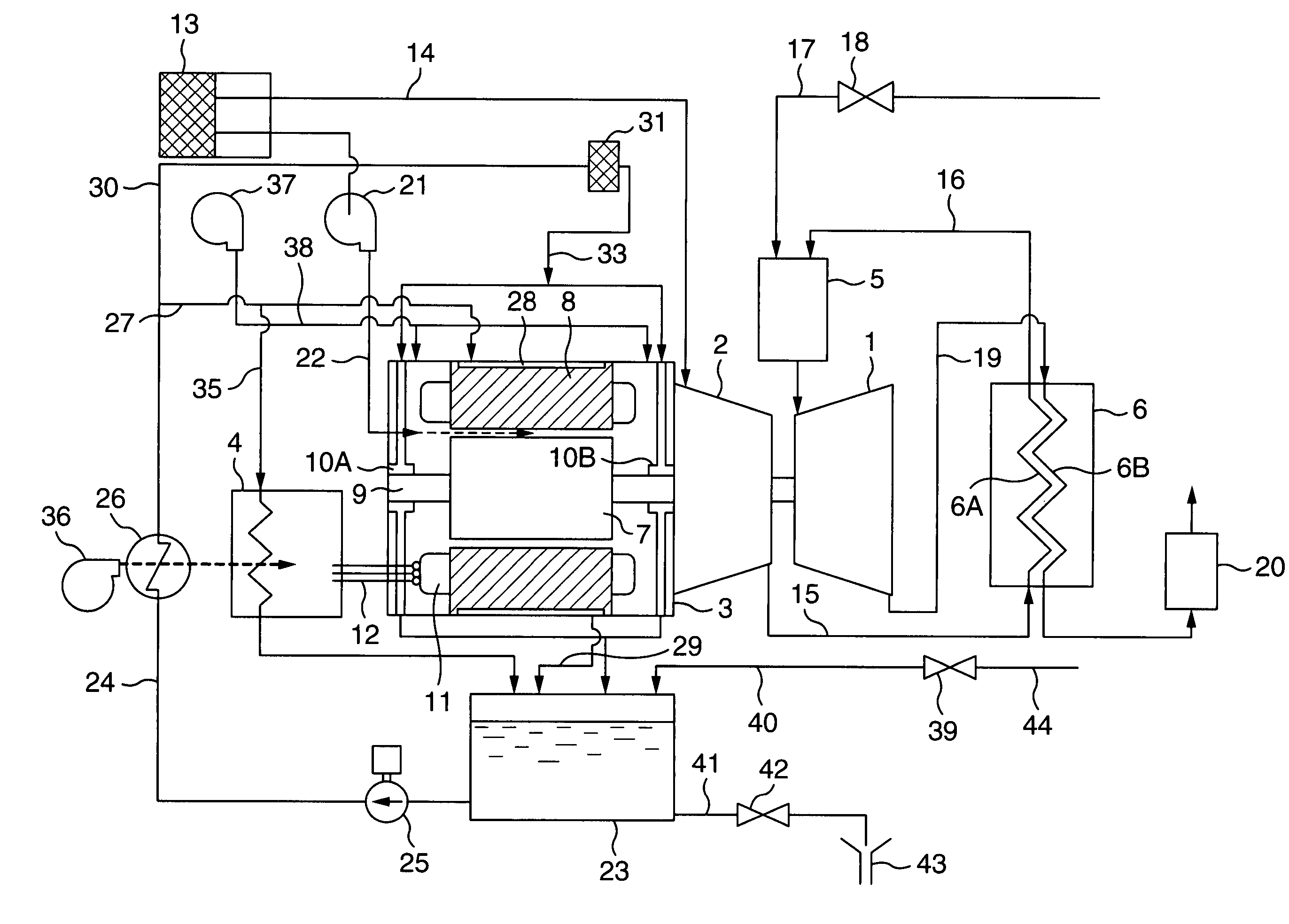
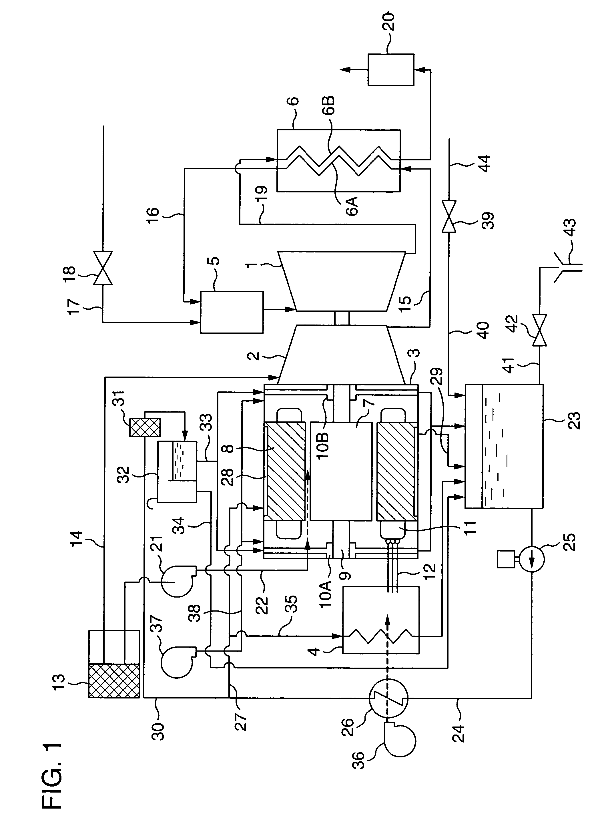
[0026]Explanation will be hereinbelow made of a gas turbine power plant in the present invention, as shown in FIG. 1.

[0027]Referring to FIG. 1, the gas turbine power plant mainly composed of a gas turbine 1, a compressor 2 coaxial with the gas turbine 1, a generator 3 coaxial with the compressor 2, a power converter 4 for converting an output power generated by the generator 3 into a power depending upon a load, a combustor 5 for mixing compressed gas produced from the compressor 2 with fuel which is fed separately so as to burn the fuel so as to produce combustion gas which is then fed into the gas turbine 1, a regenerative heat-exchanger 6 for heat-exchange between exhaust gas from the gas turbine 1 and the compressed gas from the compressor 3.

[0028]The generator 3 is a permanent magnet type three-phase a.c. generator composed of a rotor 7 incorporating permanent magnets for generating magnetic fields, and a stator 8 surrounding the rotor 7. The rotor 7 has a rotary shaft 9 which ...

second embodiment

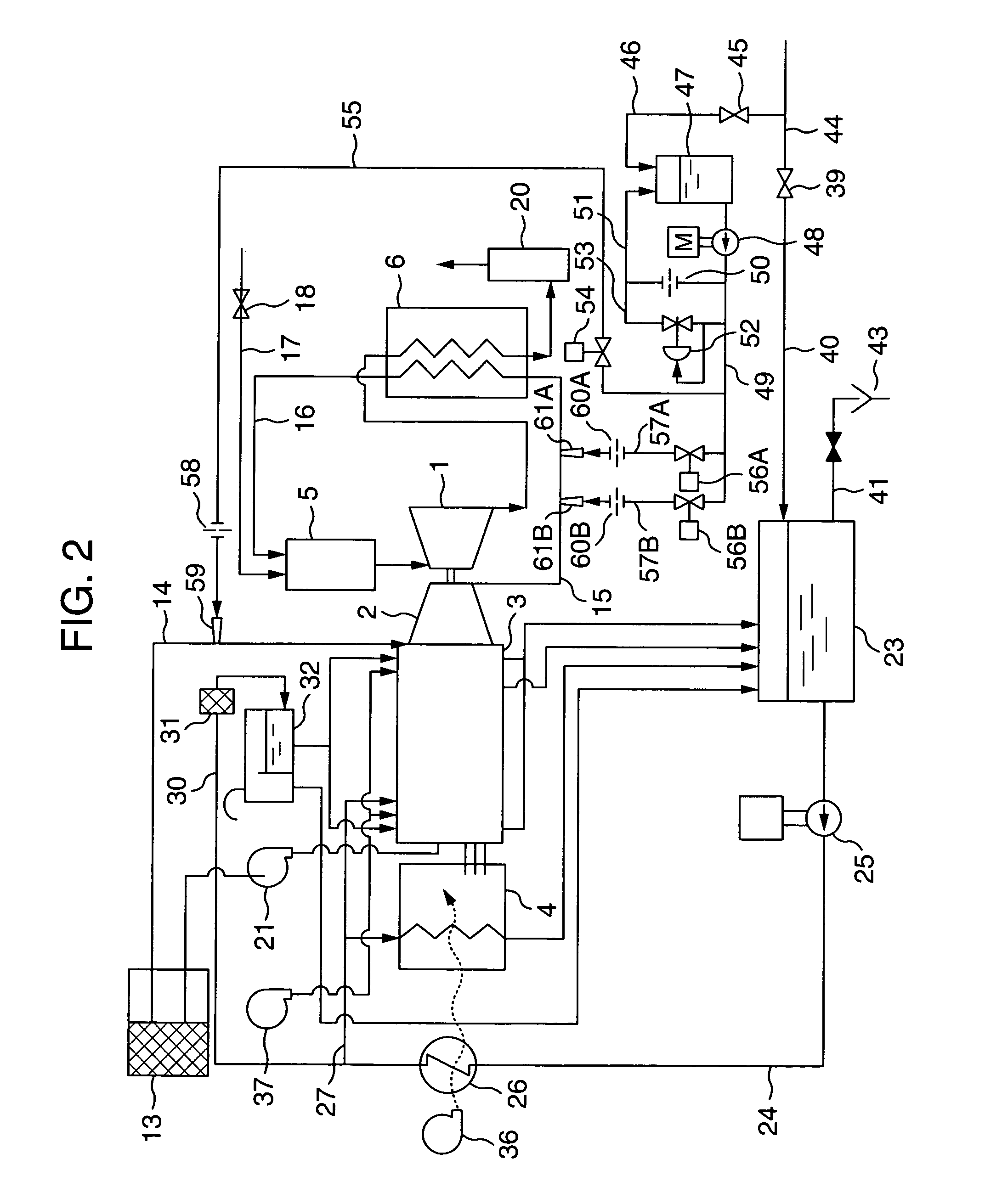
[0057]It is noted that although explanation has been made of the spray water supply system incorporating the two spray water nozzles 61A, 61B on the discharge side of the compressor 2 in the second embodiment, more than two spray water nozzles may be provided in the spray water supply system in order to increase the quantity of spray water.

[0058]Referring to FIG. 3 which shows a gas turbine power plant in a third embodiment of the present invention, the configuration of the third embodiment is basically the same as that of the second embodiment shown in FIG. 2, except the following two points: that is, as a first point, the provision of a flow regulating valve 62 in the pipe line 57 for the spray water nozzle 61 opened to the discharge pipe 15 for the compressor 2, downstream of the valve 56, and as a second point, the provision of such a configuration that a water level detected by a level gage 64 provided in the spray water tank 47 is transmitted to a valve 63 which is provided in...

fourth embodiment

[0061]Explanation will be specifically made of the fourth embodiment, the pipe line 40 connected to the cooling water tank 23 is connected thereto with the water supply pipe 44 which is provided with a shut-off valve 66 and a filter 67 and from which a pipe line 68 branches between the filter 67 and the valve 39. The pipe line 68 is connected on the downstream side thereof with a valve 69, a water feed pump 70, a chlorine removable filer 71 and a reverse osmosis membrane filter 72 in the mentioned order, and is communicated with the spray water tank 47 through the intermediary of a valve 73 on one hand, and with the pipe line 44 connected to the cooling water tank 23, through the intermediary of a valve 74 on the other hand, downstream of the reverse osmosis membrane filter 72. Further, drain water from the reverse osmosis membrane filter 72 is led into the drain port 43 by way of a valve 75. The level gage 64 provided in the spray water tank 47 is electrically connected to the wate...


PUM


Abstract

Provided is a gas turbine power plant in which a rotor of a generator is journalled by water lubrication bearings into which a part of cooling water for cooling the generator is fed. Since the lubrication water has a viscosity lower than that of lubrication oil, it is possible to provide a gas turbine power plant with less energy loss resulting in lower power consumption for accessories, and in high power generation efficiency.

Description

BACKGROUND OF THE INVENTION[0001]The present invention relates to a gas turbine power plant which is preferably used as a private power plant installed in a building for a shop, a hospital or the like.[0002]In general, of gas turbine power plants used as private power plants, a turbine power plant having a relatively large capacity utilizes oil lubrication bearings as bearings for a generator, as disclosed in JP-A-2002-221090. The gas turbine power plant having the oil lubrication bearings as disclosed in the above-mentioned document, causes a high energy loss through the bearings due to viscosity of lubrication oil, and in addition, since a lubrication oil feed pump requires a higher power for feeding the lubrication oil to the bearings, power consumption for driving accessories becomes large. As a result, the efficiency of power generation of the gas turbine power plant having the oil lubrication bearings is low.SUMMARY OF THE INVENTION[0003]An object of the present invention is t...

Claims


Application Information

Patent Timeline
Patent Type & Authority Patents(United States)
IPC IPC(8): F02C7/12F02C6/00H02K9/00F02C7/06
CPCF01D15/10F01D25/125F01D25/20F02C3/305F02C7/08F02C7/10F02C7/143F02C7/06F05D2260/212F05D2240/53
Inventor NAKANO, SUSUMUDODO, SATOSHITSUBOUCHI, KUNIYOSHIYAGI, MANABUSAWADA, ITSUROUINOUE, TOMOAKIHEMMI, MAKOTO
Owner HITACHI LTD
Why Eureka
Try Eureka