Seat

a seat and seat technology, applied in the field of seats, can solve the problems of insufficient restoring force, heavy weight, weak pressure, etc., and achieve the effects of reducing the constant spring, increasing the tension, and increasing the stability of the seated postur

Active Publication Date: 2010-06-08
DELTA TOOLING CO LTD
View PDF31 Cites 30 Cited by
  • Summary
  • Abstract
  • Description
  • Claims
  • Application Information

AI Technical Summary

Benefits of technology

[0013]In this way, the seat which is the first aspect of the present invention can stabilize the seated posture while mitigating pain and numbness of the seated person.
[0078]In the seat which is the twenty-first aspect of the present invention, the cushion material has, at the portions between the left-right direction central portion and the left-right direction both end portions, elastic members which elongate more easily in the left-right direction than the central portion and the both end portions. Therefore, with a simple structure, the aforementioned function of generating tension fields which conform even more to the shape of the human body is realized.

Problems solved by technology

However, in such a structure, there are the problems that there is the sensation that the restoring force is insufficient and that the weight is heavy.
Therefore, this becomes a cause of the supporting pressure becoming strong and a sensation that a foreign object exists arising.
Further, if this acts over a long time period, there is the problem that pain arises in the muscles at the peripheries of the aforementioned ischia, coccyx, shoulder blades and the like.
In particular, the muscles and the blood vessels in the peripheries beneath the ischial tuberosities, which support the majority of the body weight of the human body, are compressed, and there are cases in which pain or numbness due to interruption in blood circulation arises.
Therefore, the problem is known that it is easy for there to arise a phenomenon, which is the so-called hammock sensation phenomenon, in which it is easy for the seated person to move in the front-rear and left-right directions within the frame, and due to the input of vibration at the time when the vehicle travels for example, the seated posture of the seated person changes or the seated person slides forward on the seat.

Method used


Image

  • Seat
  • Seat
  • Seat

Examples


Embodiment Construction

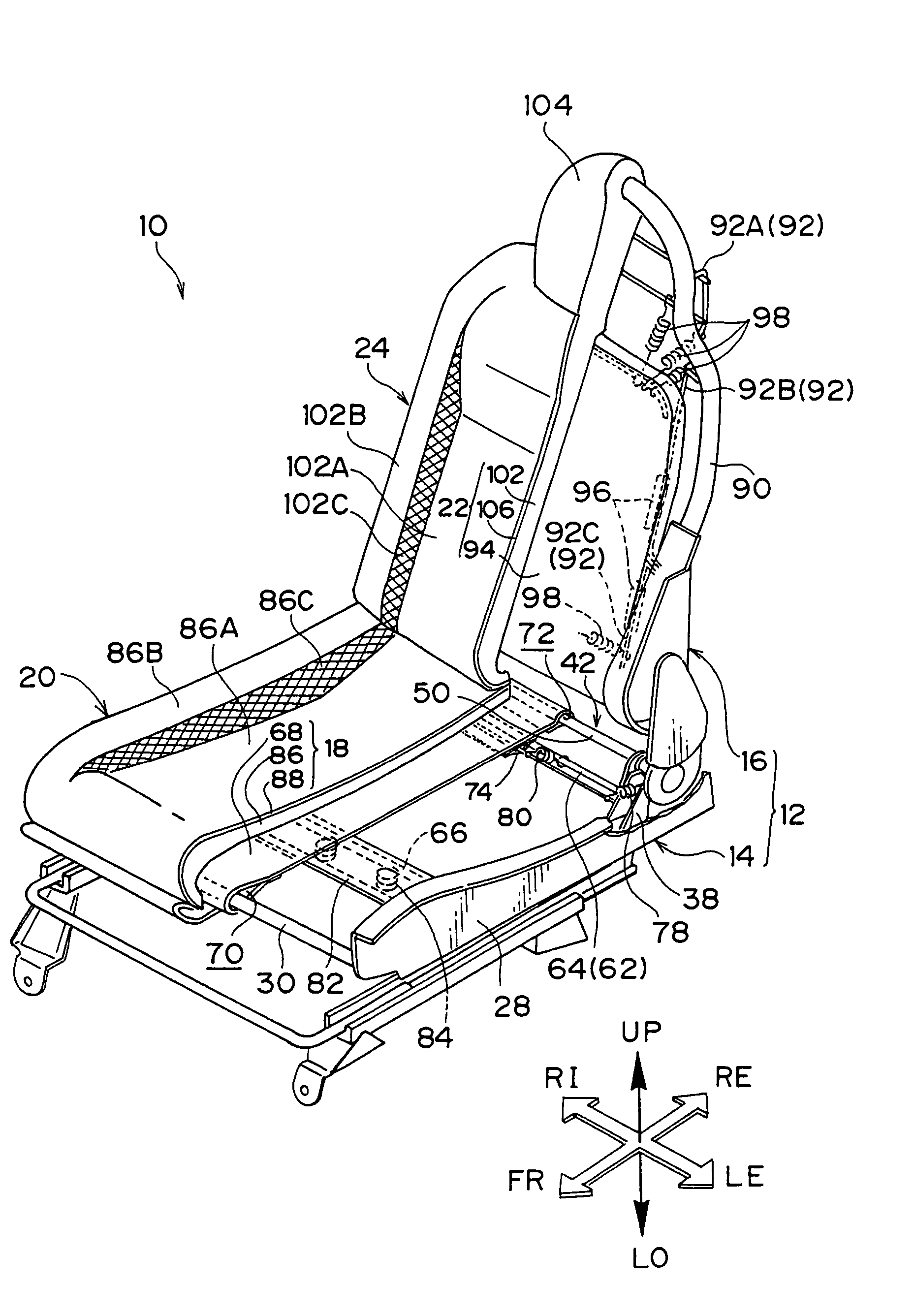
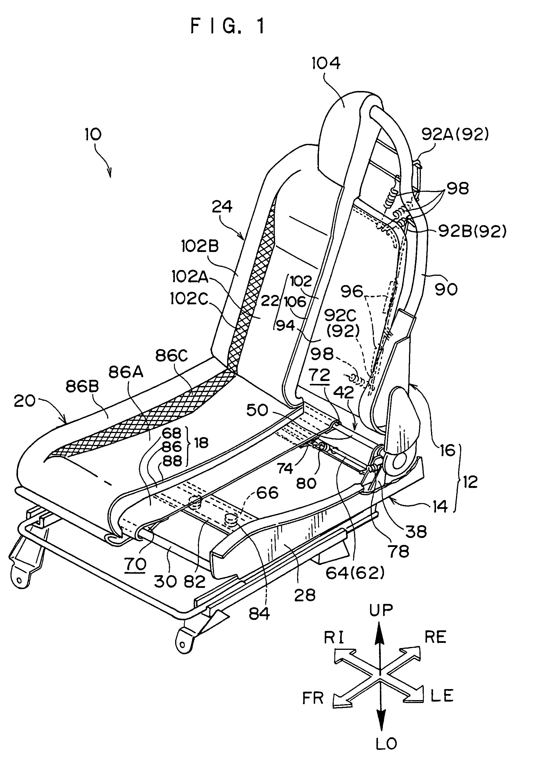
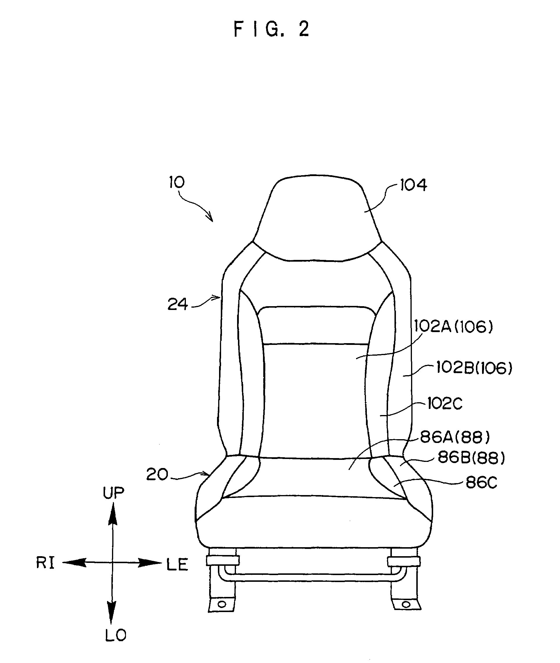
[0108]A vehicle seat 10, which serves as a seat relating to an embodiment of the present invention, will be described on the basis of FIGS. 1 through 24. Note that arrow UP, arrow LO, arrow FR, arrow RE, arrow RI and arrow LE shown appropriately in the respective drawings respectively denote the front direction (traveling direction), the rear direction, the upward direction, the downward direction, the rightward direction, and the leftward direction, with the traveling direction of the vehicle in which the vehicle seat 10 is installed being the reference. When up, down, front, rear, right, left are to merely be designated hereinafter, they correspond to the directions of the aforementioned respective arrows.

[0109]In FIG. 1, the overall structure of the vehicle seat 10 is shown in a perspective view, a portion of which is cut away. A front view of the vehicle seat 10 is shown in FIG. 2. As shown in these drawings, the vehicle seat 10 has a seat frame 12. The seat frame 12 is structur...


PUM


Abstract

At a vehicle seat 10, a cushion material 18 is provided at a frame 14 for a sitting portion of a seat frame 12, such that a seat cushion 20 is formed. An upper cushion member (three-dimensional solid knit fabric) 86, which is a surface layer portion of the cushion material 18, is stretched at the frame 14 for the sitting portion, and is layered on a cloth spring material 18 which is a lower layer portion of the cushion material 18. When the cloth spring material 68 is pressed and flexes downward due to pushing-against force which is based on body weight of a seated person at a time of sitting on the seat cushion 20, at regions of the cloth spring material 68 which are pushed by ischial tuberosities of the seated person, tensile forces of extension coil springs 80, which are forces in the pushing direction, act, and directions of tension of the cushion material 18 are in three dimensions.

Description

TECHNICAL FIELD[0001]The present invention relates to a seat, and in particular, to a seat such as a vehicle seat which is installed in a vehicle, or the like.BACKGROUND ART[0002]There is conventionally known, as a vehicle seat, a vehicle seat having a cushion material formed from polyurethane foam (hereinafter called urethane). As the cushion structure of such a vehicle seat, a structure is widely used in which a cushion material made of urethane is placed on a plate or a spring material, such as a contour mat (trade name) or the like provided at a seat frame or a seat back frame, and these are wrapped in a fabric material.[0003]Therefore, it is known that the shape (the design shape) and the elastic characteristic of the cushion material have a great effect on the body pressure dispersability of the seated person and the vibration absorbability. Further, by structuring the cushion material by layering urethanes which have various characteristics, a cushion material can be obtained...

Claims


Application Information

Patent Timeline
Patent Type & Authority Patents(United States)
IPC IPC(8): B60N2/54B60N2/58B60N2/70
CPCB60N2/58B60N2/7011B60N2/7094B60N2/7058B60N2/7064B60N2/7041
Inventor YASUDA, EIICHIDOI, SHUN'ICHISUNAMI, KIYOKAZUFUJITA, ETSUNORIOGURA, YUMIKAWASAKI, SEIJICHIZUKA, KAZUYOSHI
Owner DELTA TOOLING CO LTD
Why Eureka
Try Eureka