Revolvable clamp meter

a clamp meter and revolving technology, applied in the direction of instruments, base element modifications, coupling device connections, etc., can solve the problem of difficult reading for the operator, and achieve the effect of convenient turning and easy reading

Inactive Publication Date: 2010-06-08
CHUNG INSTR ELECTRONICS IND
View PDF7 Cites 5 Cited by
  • Summary
  • Abstract
  • Description
  • Claims
  • Application Information

AI Technical Summary

Benefits of technology

[0004]Therefore a novel clamp meter is provided where its jaw member and body members are capable of revolving relative to each other and the clamp meter's display panel therefore could be conveniently turned to face the operator for easy reading.

Problems solved by technology

A major inconvenience of the clamp meter is that, when the meter clamps the cable L, the display panel 411 is quite often not facing the operator of the clamp meter.
There are circumstances that, for example, when the cable L is located in a box B and the display panel 411 is facing a lateral side B1 of the box B, it is extremely difficult for the operator to read the measurement.

Method used


Image

  • Revolvable clamp meter
  • Revolvable clamp meter
  • Revolvable clamp meter

Examples


Embodiment Construction

[0015]The following descriptions are exemplary embodiments only, and are not intended to limit the scope, applicability or configuration of the invention in any way. Rather, the following description provides a convenient illustration for implementing exemplary embodiments of the invention. Various changes to the described embodiments may be made in the function and arrangement of the elements described without departing from the scope of the invention as set forth in the appended claims.

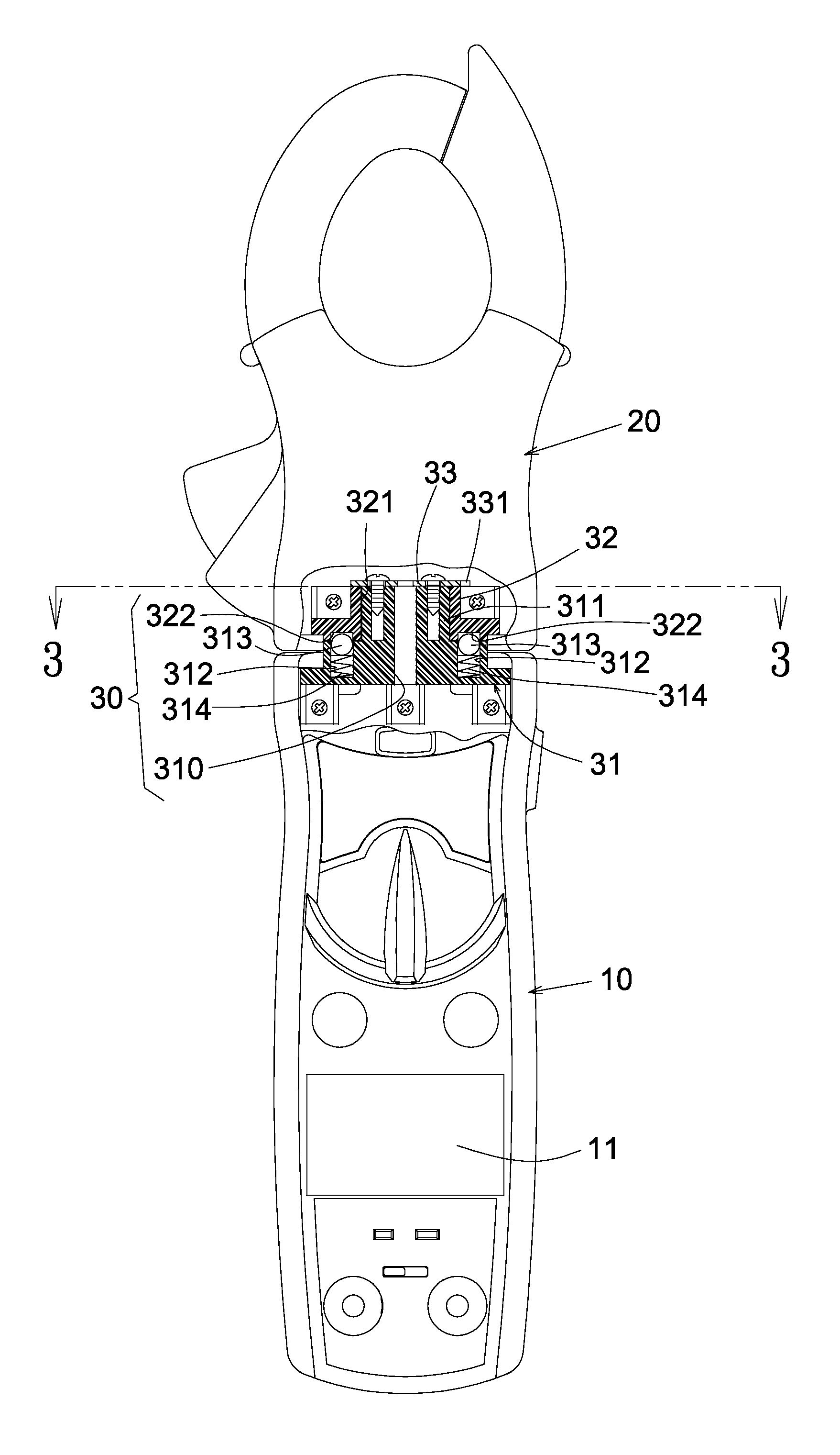
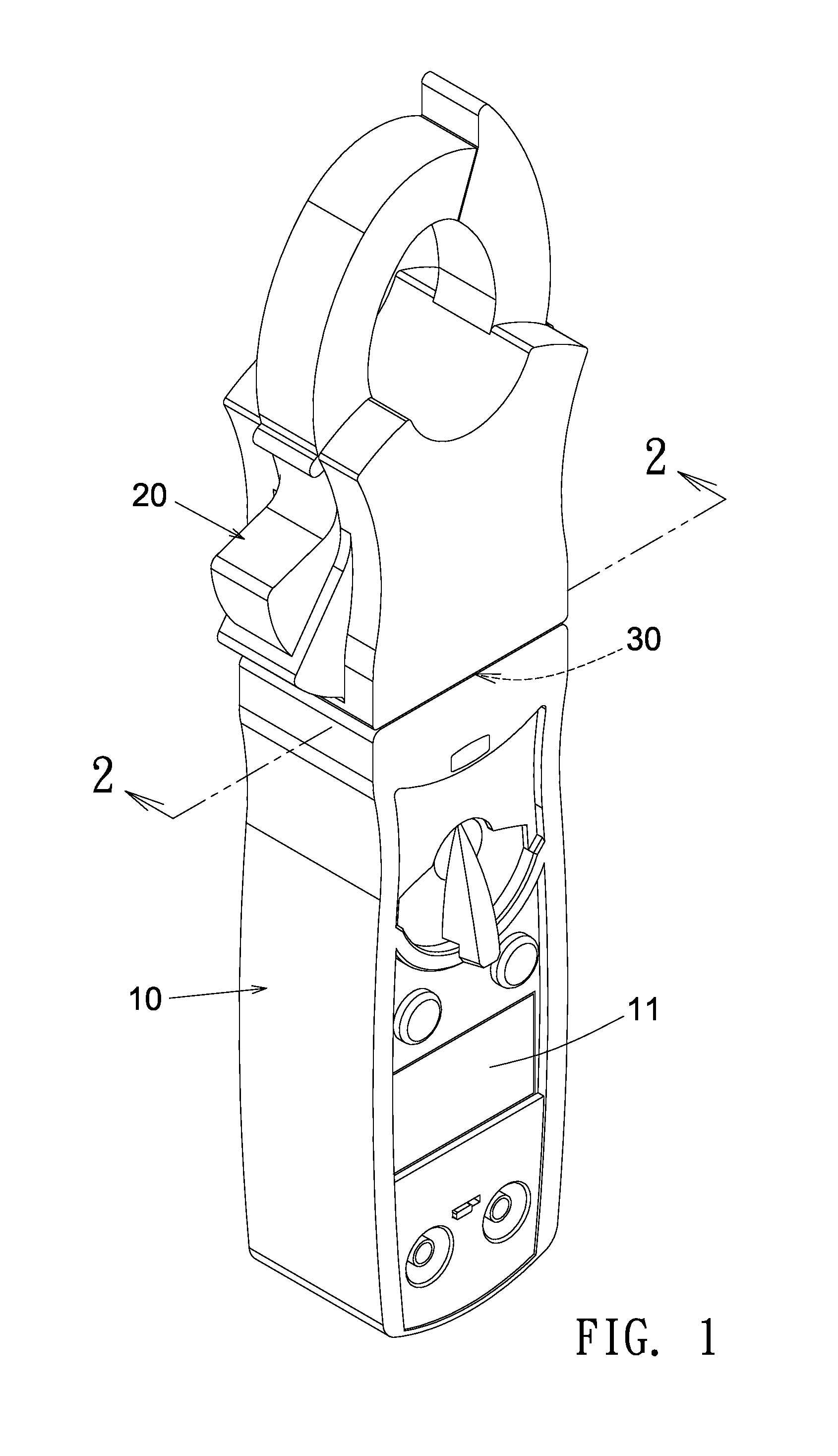
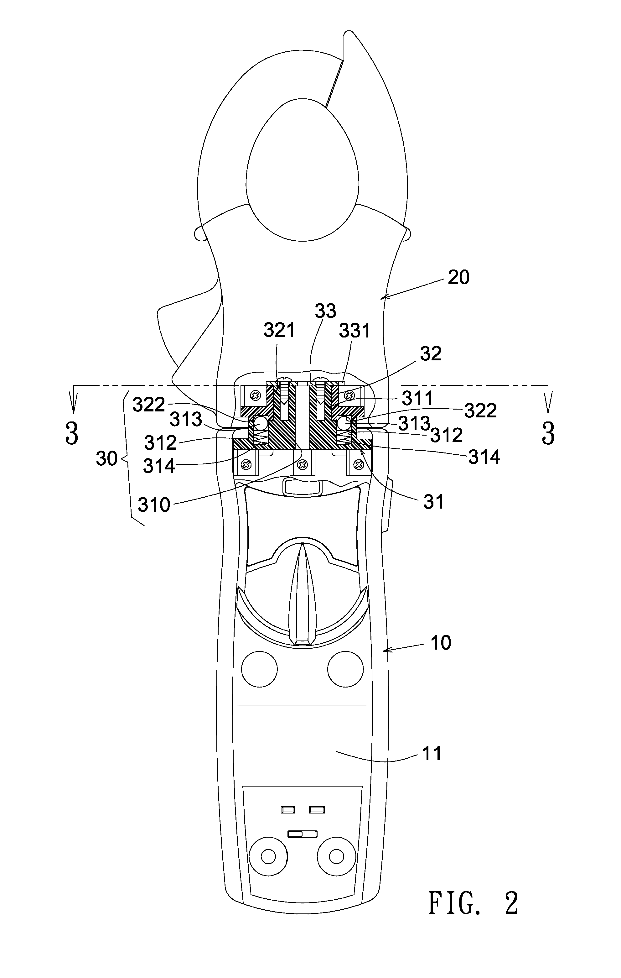
[0016]As shown in FIGS. 1 to 6, a clamp meter according to an embodiment of the present invention contains a body member 10 having a display panel 11, and a jaw member 20 at an end of the body member 10 for clamping around a cable L. The clamp meter measures a current or other electrical characteristic of the cable L and displays the measurement in the display panel 11. The clamp meter further contains a revolving member 30 composed of a first base 31 and a second base 32 located on the interfacing ...


PUM


Abstract

The clamp meter contains a revolving member configured between the meter's body member and jaw member. The revolving member is composed of a first base and a second base located on the interfacing sides of the body member and the jaw member, respectively. The first base and the second base are revolvably joined together by an axle extended axially from the body member into the jaw member via the first and second bases' aligned axle holes. The first base has at least a roller ball elastically embedded in a concave and exposed towards the second base. The roller ball would roll into one of a number of notches of the second base as the base and jaw members are rotated relative to each other, thereby creating a number of preset configurations of the included angle between the body and jaw members.

Description

TECHNICAL FIELD OF THE INVENTION[0001]The present invention generally relates to clamp meters, and more particularly to a clamp meter whose jaw member and body member are capable of revolving relative to each other so that the clamp meter's display panel could be conveniently turned to face the operator for easy reading.DESCRIPTION OF THE PRIOR ART[0002]As shown in FIG. 7, a clamp meter is an electrical device having a body member 41 and a jaw member 42. The jaw member 42 has two jaws which open to allow clamping around an electrical cable L. This allows the electrical current or other electrical characteristic in the cable L to be measured, without having to make physical contact with the cable L, and the measurement is shown in a display panel 411 of the body member 41.[0003]A major inconvenience of the clamp meter is that, when the meter clamps the cable L, the display panel 411 is quite often not facing the operator of the clamp meter. Either the clamp meter has to be twisted or...

Claims


Application Information

Patent Timeline
Patent Type & Authority Patents(United States)
IPC IPC(8): G01R1/20G01R1/04G01R19/00
CPCG01R1/22
Inventor LIU, SHAW-LIN
Owner CHUNG INSTR ELECTRONICS IND
Why Eureka
Try Eureka