Unlock instant, AI-driven research and patent intelligence for your innovation.

Method for the monitoring of transmissions of a bidirectional interface

a technology of bidirectional interface and transmission monitoring, which is applied in the direction of frequency-division multiplex, data switching network, instruments, etc., can solve the problems of non-digital bidirectional and difficulty in adhering to requirements

Inactive Publication Date: 2010-06-08
TRIDONIKATKO GMBKH & KO KG
View PDF5 Cites 1 Cited by
  • Summary
  • Abstract
  • Description
  • Claims
  • Application Information

AI Technical Summary

Benefits of technology

[0009]In accordance with a first variant for a possibly required correction of the temporal bit length, the temporal bit length can be detected by starting a counter at a first flank and stopping the counter at the following flank, wherein then depending on the information gained the bit lengths of the following transmissions can be corrected by software. With a second variant the temporal bit length can be determined through the reception branch starting from the temporal difference between the input of the start flank of the bit in the interface and the passing on of this start flank on an attached bus, and correspondingly the required period for the bit length corrected. Both variants offer the advantage that for a correct adjustment of the bit length no additional hardware elements are required in the interface but instead all corrections can be carried out by software.

Problems solved by technology

Since however the interfaces being used are normally constructed as economically as possible, and particularly the transmission branch responsible for the realization of the bit lengths is configured considerably more complexly and therefore more susceptible to component tolerances than the reception time is, there arises the problem that this requirement can be adhered to only with difficulty.
Similar problems also arise with non-digital bidirectional interfaces with which the signals distributed by the transmission branch also must likewise fulfil certain requirements, which—due to the trend towards cost saving mentioned above—can be complied with only with difficulty.

Method used


Image

  • Method for the monitoring of transmissions of a bidirectional interface
  • Method for the monitoring of transmissions of a bidirectional interface
  • Method for the monitoring of transmissions of a bidirectional interface

Examples


Embodiment Construction

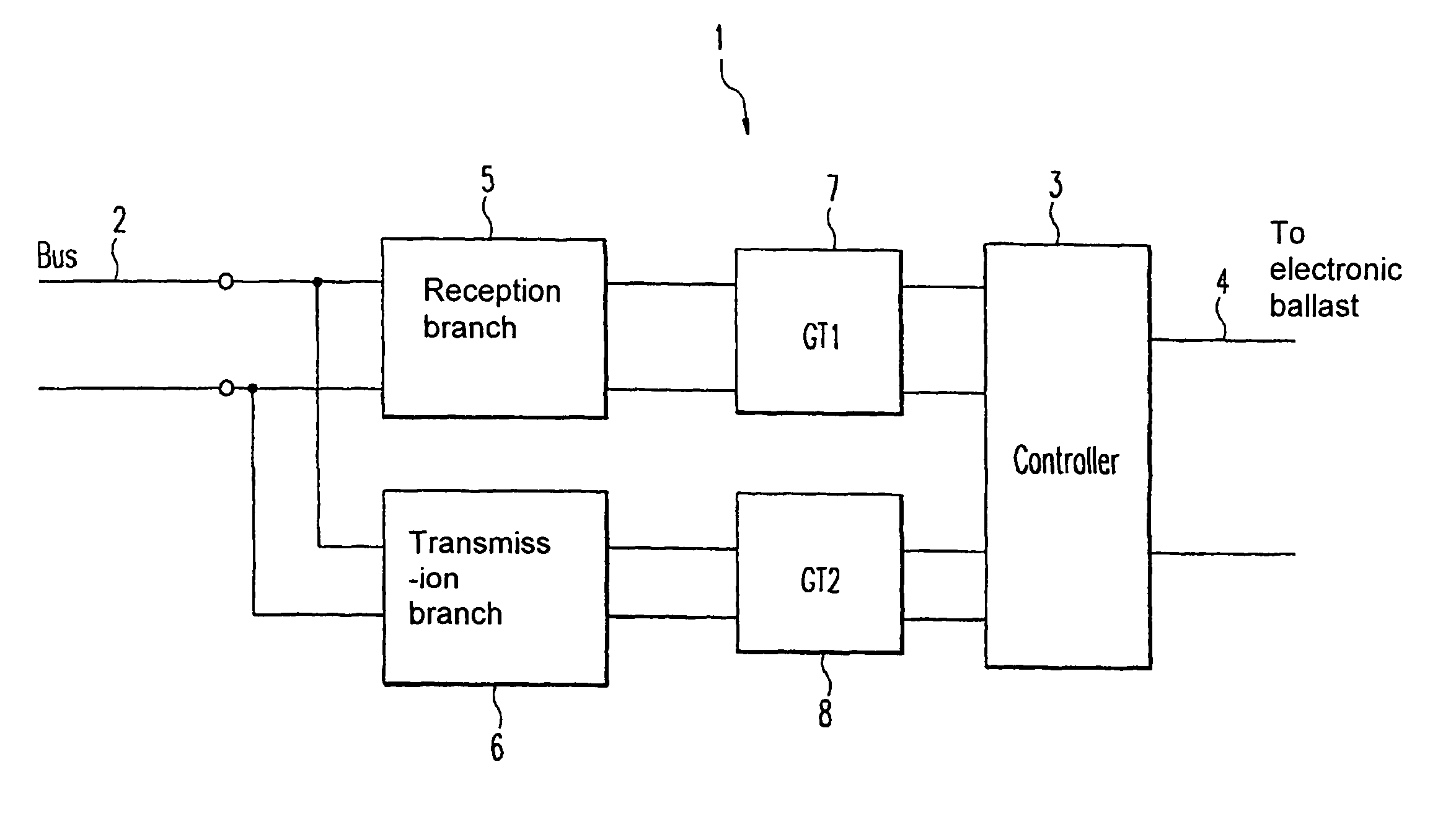
[0018]Firstly FIG. 1 shows generally the construction of a bidirectional interface 1 which is configured for the reception and for the transmission of data via the two lines of a bus line system 2. The construction of this interface 1 corresponds substantially to the classic construction of bidirectional interfaces since the measures mentioned above according to the invention are primarily of software-related nature are and do not require use of additional hardware components.

[0019]A component of the interface 1 is correspondingly a controller 3 which is responsible for the data reception and the data transmission and is in connection with a device to be controlled via output lines 4. In the case of the present exemplary embodiment it is to be assumed that the device to be controlled is a device for operating illumination means, in particular for a lamp as for example with a gas discharge lamp, LEDs or halogen illumination element. An electronic ballast (EVG) is preferred for gas di...


PUM


Abstract

A method for the monitoring of transmissions in a transmission branch of a bidirectional interface, which besides the transmission branch has a reception branch standing in connection with the transmission branch, has the steps a) sending out of information by means of the transmission branch, and b) evaluation of defined characteristics of the sent information via the reception branch of the same interface, whereby preferably depending on the evaluation of the sent information a setting of parameters of the transmission branch is effected, so that future information is sent out with use of these parameters.

Description

BACKGROUND OF THE INVENTION[0001]The invention relates to a method for the monitoring of transmissions in a transmission branch of a bidirectional interface, in particular a digital bidirectional interface. Furthermore the invention relates to a lamp operating device for operating a lamp which has a corresponding bidirectional interface for data interchange.RELATED TECHNOLOGY[0002]Illumination systems for the illumination of large complexes or buildings, in which a plurality of luminaires arranged decentrally distributed are controlled by a central control unit, require the possibility of an extensive and reliable data interchange due to the variety of functions available. Whilst with earlier illumination systems it was known solely to transmit to the various luminaires switch-on and switch-off commands from a central control unit, modern illumination systems now provide the possibility of a data transfer from the luminaires to the central control unit, to transmit for example infor...

Claims


Application Information

Patent Timeline
Patent Type & Authority Patents(United States)
IPC IPC(8): H04L12/26
CPCG06F13/4072H05B37/0254H04L12/40032H05B47/18
Inventor BOECKLE, REINHARDSTRIETZEL, CARSTENJUEN, REINHOLD
Owner TRIDONIKATKO GMBKH & KO KG