Door shutter

a door shutter and bendable technology, applied in the direction of shutters/movable grilles, door/window protective devices, transportation and packaging, etc., can solve the problems of impaired bendability, achieve the effect of improving overall rigidity, reducing manufacturing costs, and not impairing bendability

Active Publication Date: 2010-06-15
NIFCO INC
View PDF9 Cites 29 Cited by
  • Summary
  • Abstract
  • Description
  • Claims
  • Application Information

AI Technical Summary

Benefits of technology

[0012]In the invention of the second feature, by the fact that the block pieces are made to project from the underside of the main body in a condition having the lower side not joined to the main body, the overall rigidity can be improved by making the block pieces larger without impairing the bendability. As opposed to this, in the inventions of third and four features, for example, the manufacturing expense can be reduced by the fact that the block pieces and the main body are integrally formed by two-material molding method, or the like. Also, the overall rigidity can be fulfilled by the block pieces made of hard resin, and the bending characteristic of the thin parts can be fulfilled by the main body made of soft resin.

Problems solved by technology

In other words, as the shutter, although it is preferable to make the design surface of the main body an upwardly convex curved shape, it was considered impossible in connection with that the bendability is impaired.

Method used


Image

  • Door shutter
  • Door shutter
  • Door shutter

Examples


modified example

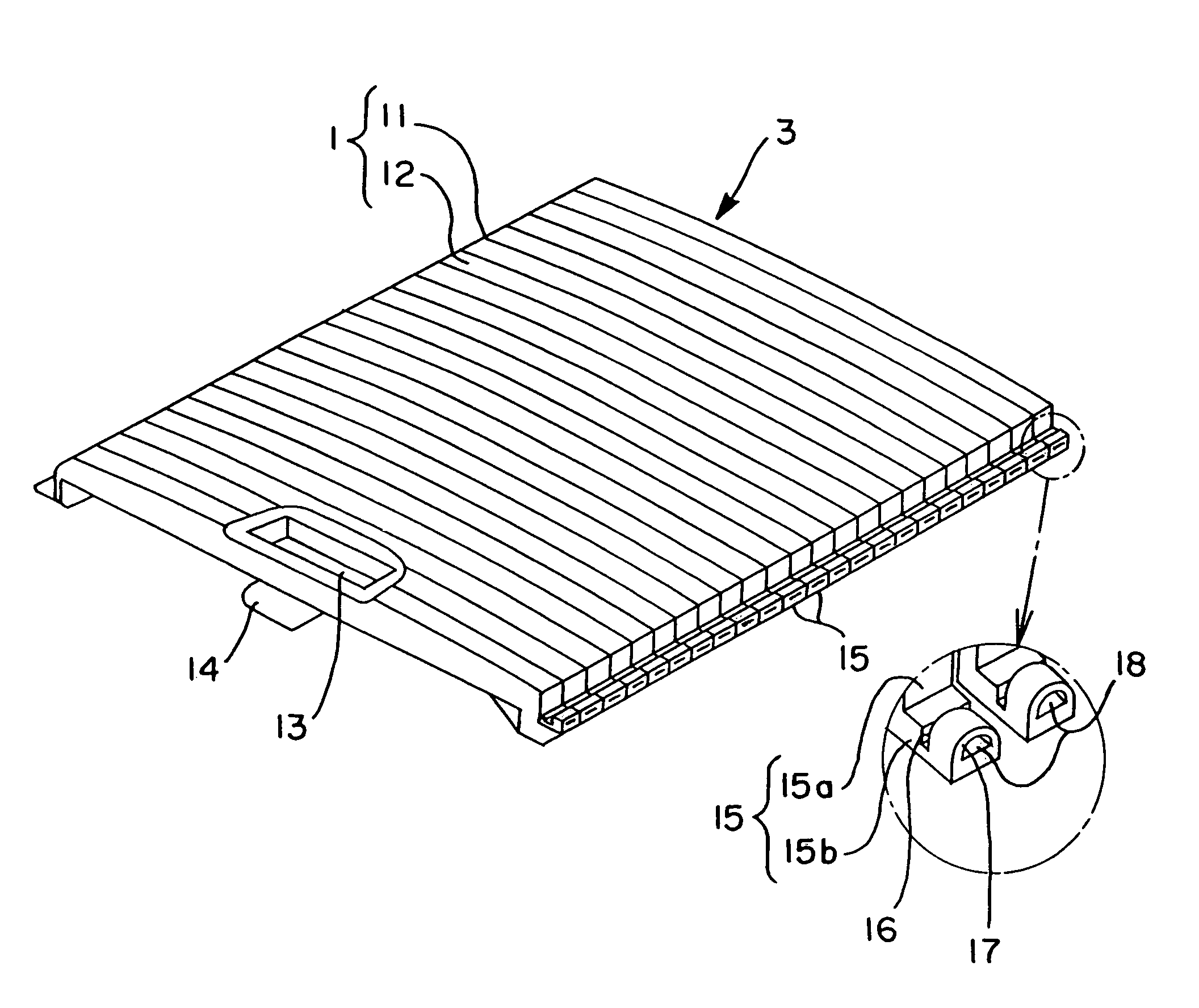
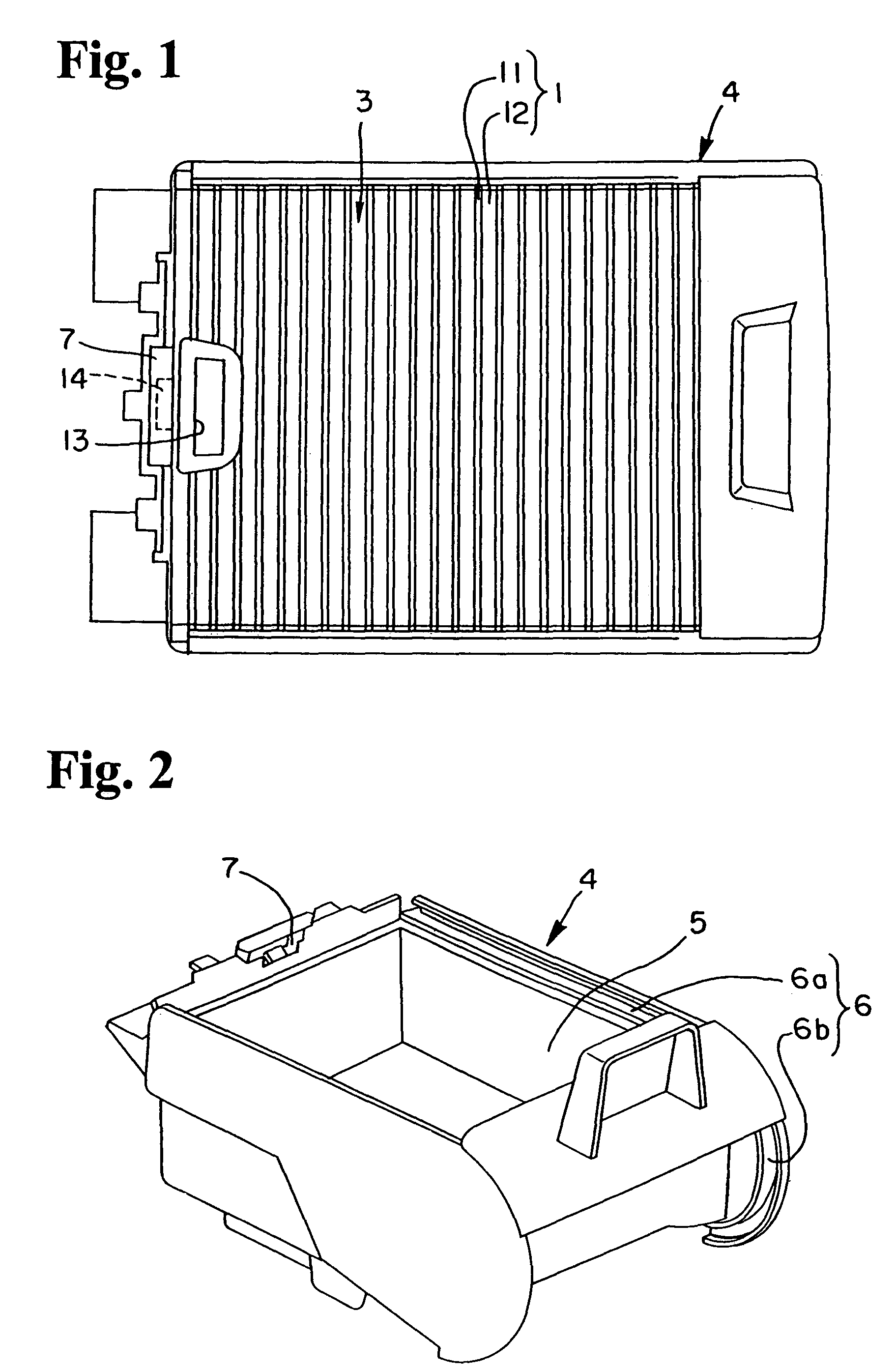
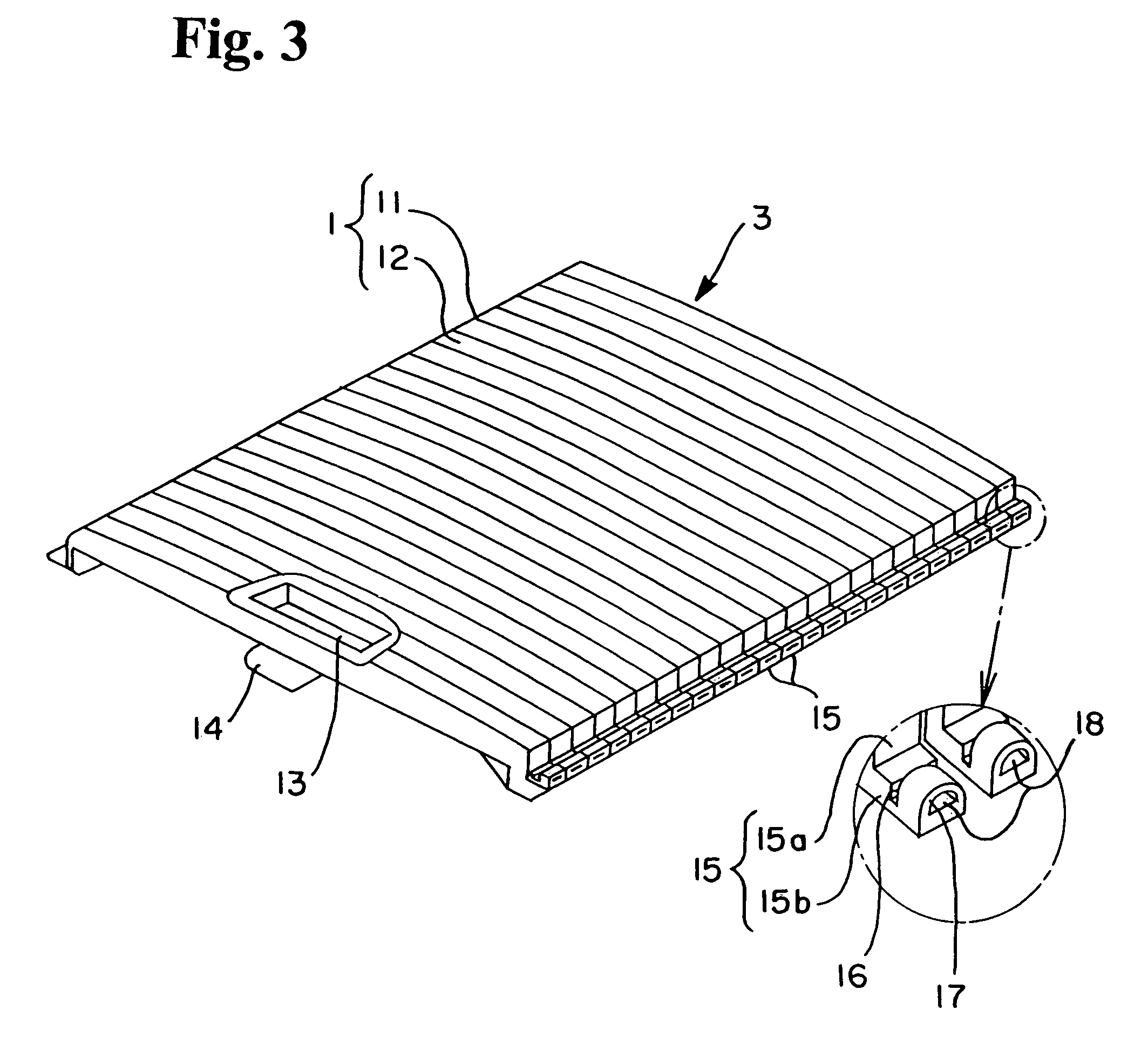
[0027]FIG. 6 shows an example having changed the shape of the above block piece. This block piece 2A is roughly T shaped in vertical section, and it is integrated on the main body 1 in a condition having the horizontal part 2a joined and the vertical part 2b not joined. In this case as well, each block piece 2A, when viewed from the underside of the shutter 3, is made to project in a condition having the horizontal part 2a of the T shape buried in the part 12 between thin part 11 and thin part 11 of the main body 1 and in a condition having the vertical part 2b not joined with the main body 1. Thus the present invention can be modified variously except for the essential conditions specified in the claims. Also, it is optional concerning the use of the shutter 1, the shape of the device-side guide groove, and the like.


PUM


Abstract

While a bending ability is maintained, it is possible to provide an outer appearance which is not made possible in the past. A door shutter includes a main body on a design surface side which is bent in a width direction through thin parts, and plural block pieces disposed between the thin parts on an underside of the main body, wherein an opening on a device side is opened or closed by sliding along a guide groove on the device side. On the main body, the thin parts are formed as a plane surface, and parts overlapping with the block pieces are formed in an upwardly convex curved shape.

Description

BACKGROUND OF THE INVENTION AND RELATED ART STATEMENT[0001]The present invention relates to a bendable door shutter that is slid following a guide groove on a device side.[0002]Among door shutters, there is one, as shown in Patent Document 1, having a main body on a design surface side which is bent via thin parts in the width direction, and plural block pieces (same as frame or core wood) disposed on the underside of that main body, for opening and closing a device opening by being slid following a guide groove having a curved part on the device side. Here, as the main body, a soft resin, or the like, is used in order to maintain bendability, the thin parts are formed at equal intervals, and each thin part and the parts between the thin parts are formed as a plane surface. As the block pieces, a hard resin, or the like, is used in order to give rigidity, and from the viewpoint of bendability, they are disposed integrally between the thin parts on the underside of the main body.[000...

Claims


Application Information

Patent Timeline
Patent Type & Authority Patents(United States)
IPC IPC(8): B60R7/04
CPCE06B9/15
Inventor OGAWA, ATSUSHI
Owner NIFCO INC
Why Eureka
Try Eureka