Drillable down hole tool

a technology of down hole tools and drillable, which is applied in the direction of fluid removal, borehole/well accessories, sealing/packing, etc., can solve the problems of loss of seal or damage to other well components, the longitudinal extrusion of down hole tools, and the uneven formation of separable slip elements. to achieve the effect of reducing longitudinal extrusion

Inactive Publication Date: 2010-06-15
BEAR CLAW TECH LLC
View PDF45 Cites 139 Cited by
  • Summary
  • Abstract
  • Description
  • Claims
  • Application Information

AI Technical Summary

Benefits of technology

[0011]It has been recognized that it would be advantageous to develop a device and method for setting a down hole tool in a well bore using slip rings having fracture regions that separate the slip ring into substantially equally sized slip elements. In addition, it has been recognized that it would be advantageous to develop a device and method for setting a down hole tool in a well bore using upper and lower slip rings having fracture regions that sequentially separate the lower slip ring

Problems solved by technology

Unfortunately, the down hole tools described above have some problems For example, the slip elements are often made of a cast iron ring with stress risers spaced about the ring.
Unfortunately, the rings sometimes do not fracture along the stress risers, or the stress risers do not fracture uniformly so that the separable slip elements are not evenly formed.
This uneven loading can result in movement of the down hole tool over time as it is used in the well bore and which results in an loss of seal or damage to other well components.
Another problem of the down hole

Method used


Image

  • Drillable down hole tool
  • Drillable down hole tool
  • Drillable down hole tool

Examples


Embodiment Construction

[0036]Reference will now be made to the exemplary embodiments illustrated in the drawings, and specific language will be used herein to describe the same. It will nevertheless be understood that no limitation of the scope of the invention is thereby intended. Alterations and further modifications of the inventive features illustrated herein, and additional applications of the principles of the inventions as illustrated herein, which would occur to one skilled in the relevant art and having possession of this disclosure, are to be considered within the scope of the invention.

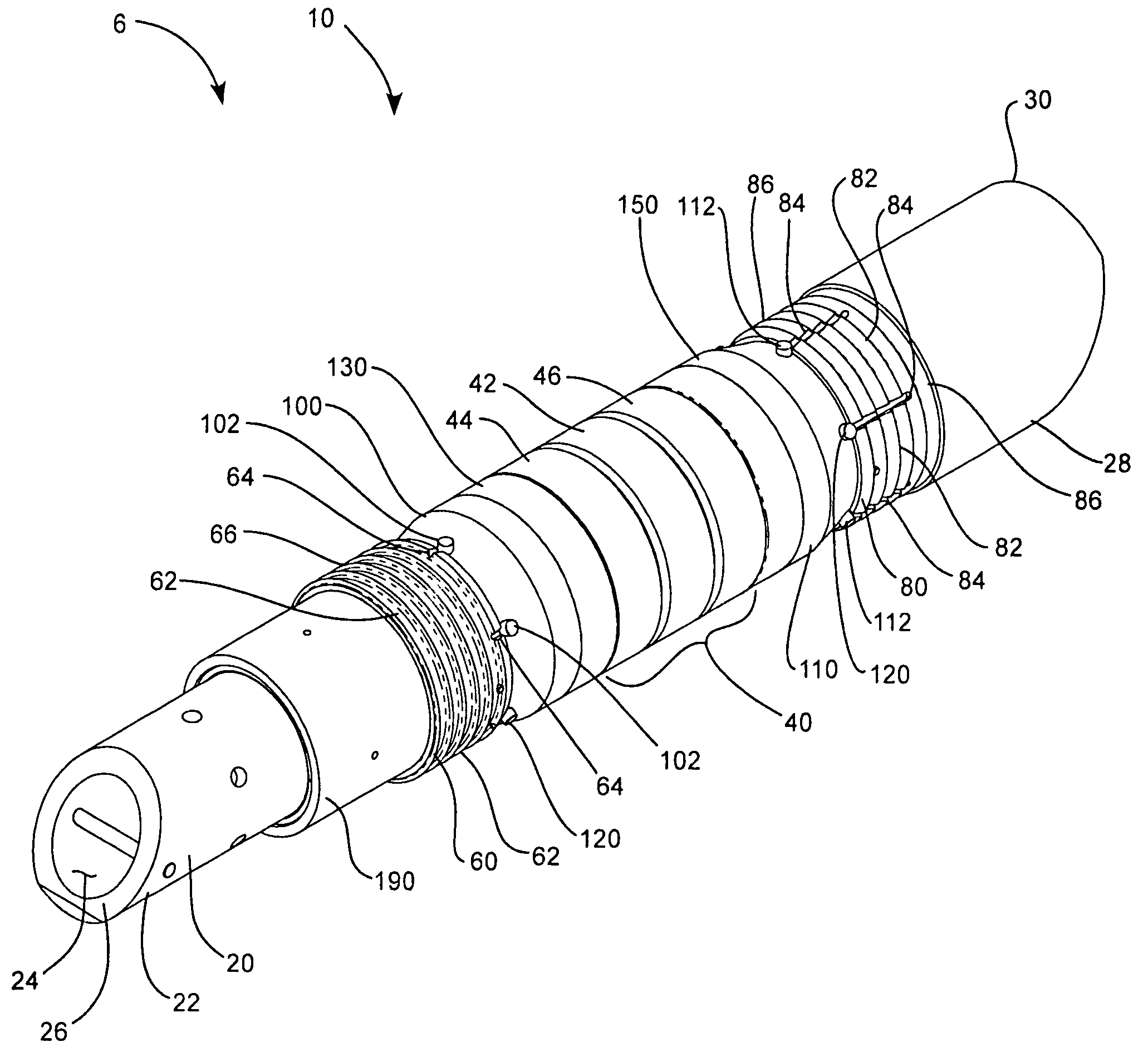
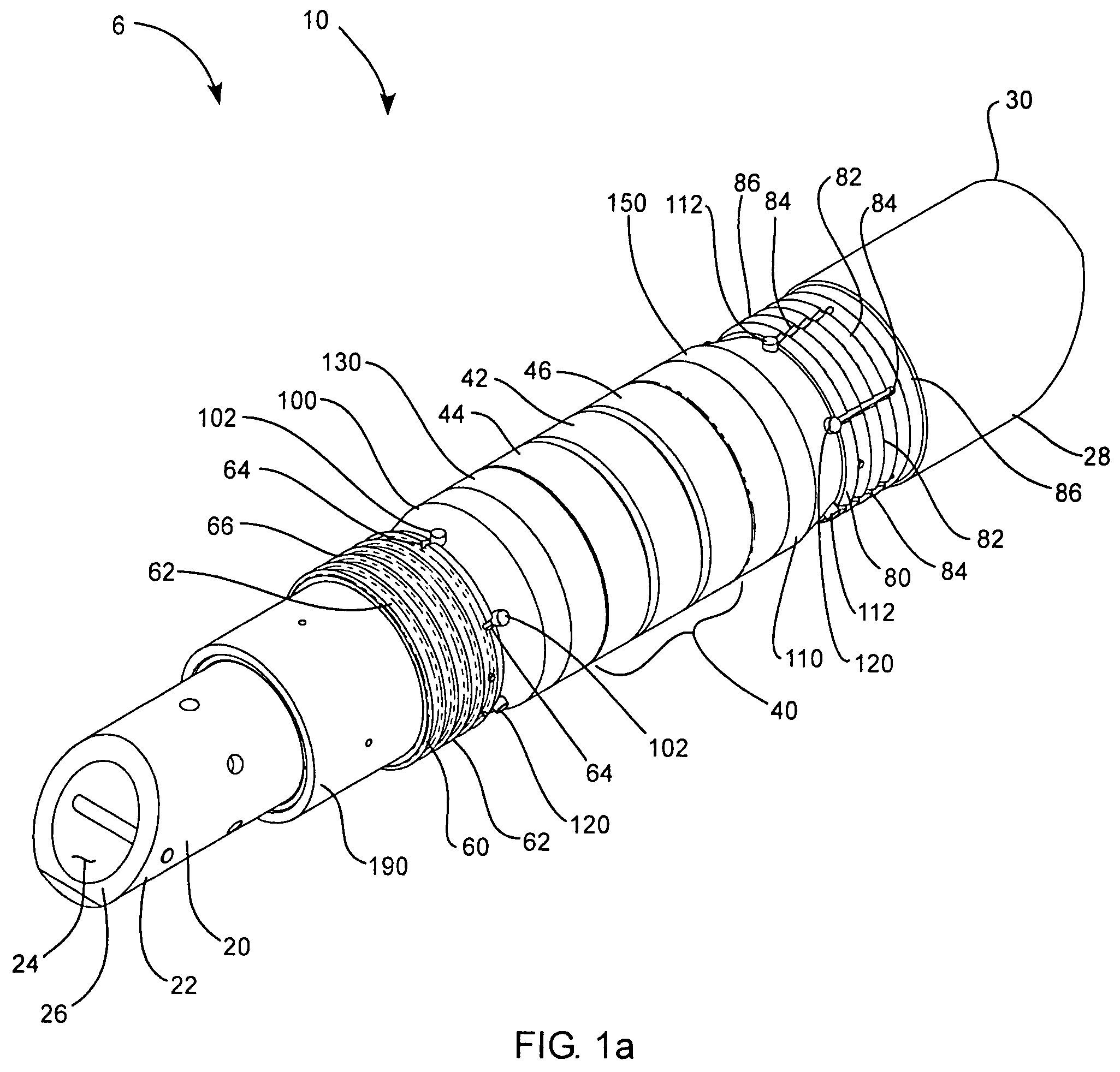
[0037]As illustrated in FIGS. 1a-4, a remotely deployable, disposable, drillable down hole flow control device, indicated generally at 10, in accordance with an embodiment of the present invention is shown for use in a well bore as a down hole tool. The down hole flow control device 10 can be remotely deployable at the surface of a well and can be disposable so as to eliminate the need to retrieve the device. One...


PUM


Abstract

A down hole flow control device used in a well bore includes a central mandrel and a packer ring disposed thereon. The packer ring is compressible along a longitudinal axis of the central mandrel to form a seal between the central mandrel and the well bore. Upper and lower slip rings are disposed on the central mandrel and include a plurality of slip segments joined together by fracture regions to form the slip rings. The fracture regions are configured to facilitate longitudinal fractures to break the slip rings into the plurality of slip segments that secure the down hole flow control device in the well bore. The upper and lower slip rings have different fracture regions from one another to induce sequential fracturing with respect to the upper and lower slip rings when an axial load is applied to both the upper slip ring and the lower slip ring.

Description

BACKGROUND OF THE INVENTION[0001]1. Field of the Invention[0002]This invention relates generally to down hole tools for use in oil and gas wells, and more particularly to down hole tools having drillable materials and metallic slips.[0003]2. Related Art[0004]Down hole tools, such as well packers, bridge plugs, fracture (“frac”) plugs, cement retainers, and the like, are commonly used in oil or gas wells for fluid control in both completion and production efficiency applications. For example, such down hole tools are often placed in the bore of a well to form a seal between the well tubing and casing in order to isolate one or more vertical portions of the well. A tool can also be placed inside the casing to isolate one elevation from another during formation fracturing and treatment operations.[0005]Down hole tools often have central mandrel with lower slip elements adjacent a lower slip wedge and upper slip elements adjacent an upper slip wedge. The slip elements are often made of ...

Claims


Application Information

Patent Timeline
IPC IPC(8): E21B23/00E21B33/12
CPCE21B33/134E21B33/1293
Inventor NISH, RANDY W.JONES, RANDY A.LAWSON, ROBIN
Owner BEAR CLAW TECH LLC
Why Eureka
Try Eureka