Double looped fuel line for a model vehicle

a model vehicle and fuel line technology, applied in the direction of machine supports, hose connections, pedestrian/occupant safety arrangements, etc., can solve the problems of remote control vehicles such as models and other reduced-size vehicles, unduly expensive vehicles to construct, and insufficient handling characteristics

Active Publication Date: 2010-06-15
TRAXXAS
View PDF15 Cites 1 Cited by
  • Summary
  • Abstract
  • Description
  • Claims
  • Application Information

AI Technical Summary

Problems solved by technology

However, despite improvements in design of vehicles over the years, vehicles remain unduly expensive to construct, expensive to maintain.
Furthermore, vehicles, in particular, remotely controlled vehicles such as models and other reduced-size vehicles, do not have optimum handling characteristics and are unduly difficult to adjust to obtain optimum handling characteristics under different driving conditions.

Method used


Image

  • Double looped fuel line for a model vehicle
  • Double looped fuel line for a model vehicle
  • Double looped fuel line for a model vehicle

Examples


Embodiment Construction

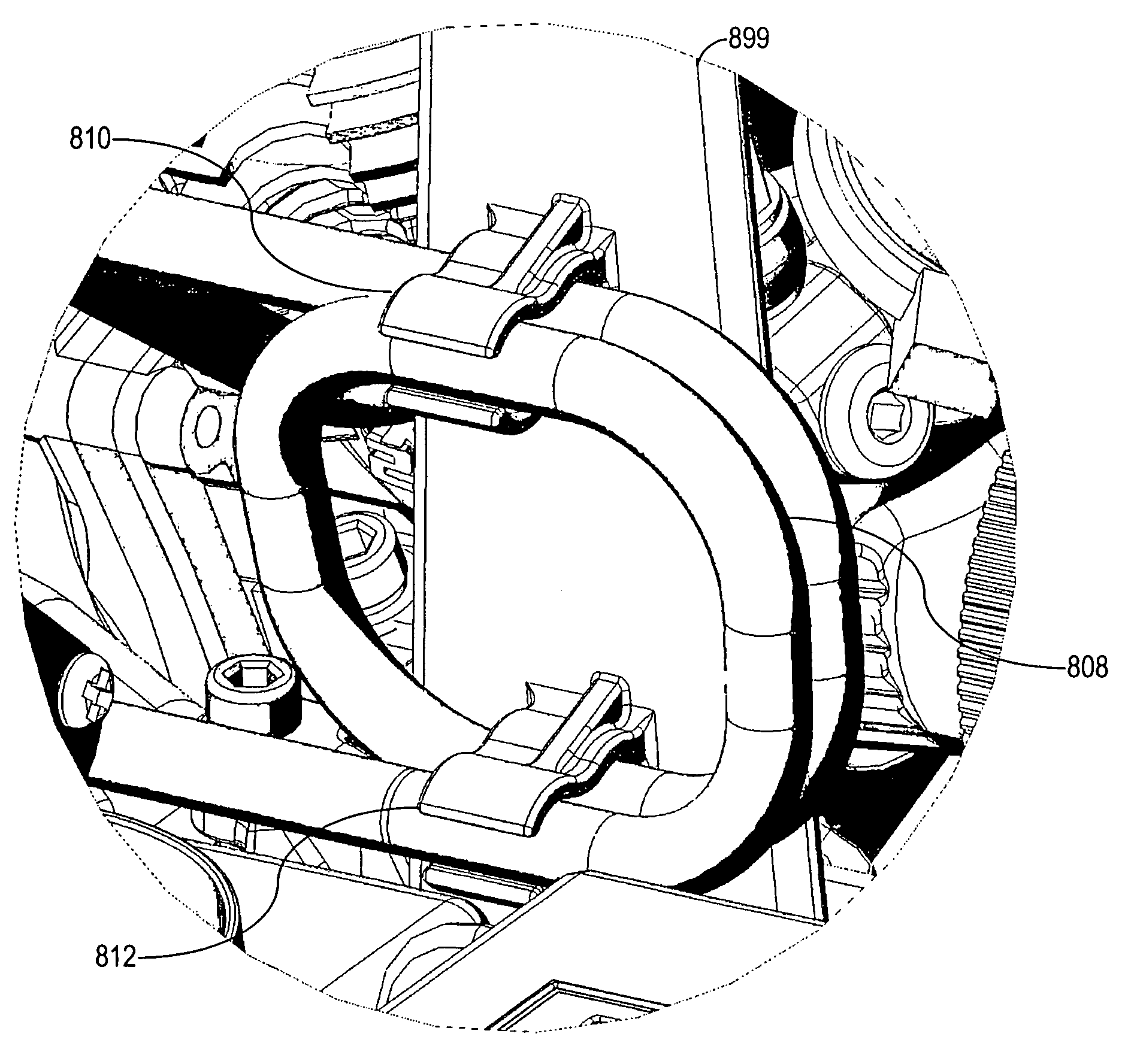
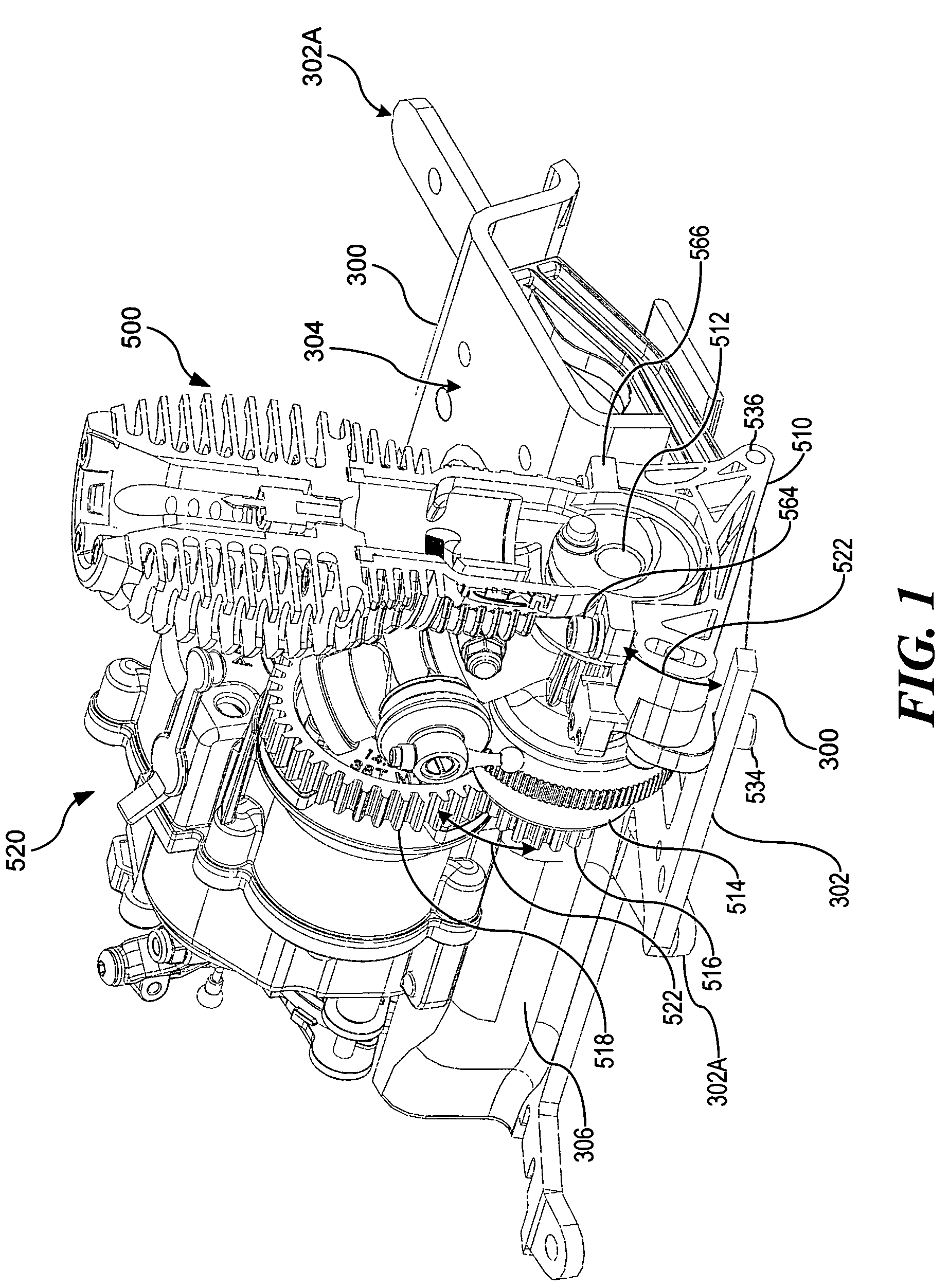
[0089]FIG. 1 illustrates a vehicle engine 500 supported by an engine mount 510 (partially shown) on the vehicle chassis 300. The engine 500 drive shaft 512 rotates a clutch bell 514 and drive gear 516 assembly that is coupled via a spur gear 518 to a transmission assembly 520. The engine mount 510 is configured to allow generally vertical movement, shown by the arrows 522, to accommodate drive and spur gears 516, 518 of different sizes or to allow engagement and disengagement of a vehicle engine with a transmission. Such gear mesh adjustment, in a generally vertical direction, reduces horizontal space needed on the chassis 300 and accommodates the multi-level design of the chassis 300.

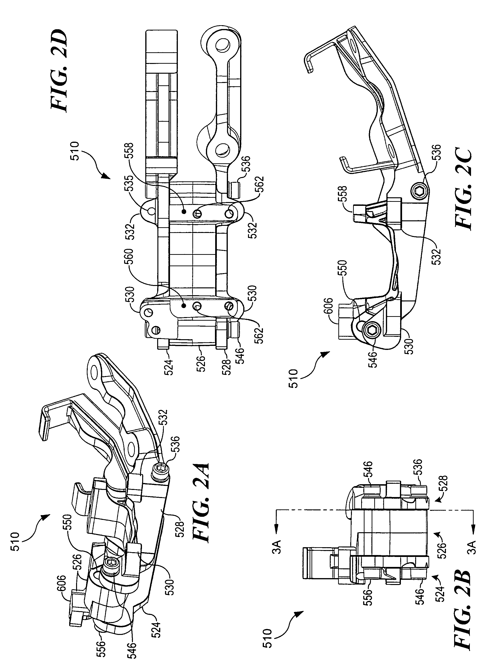
[0090]Referring now to FIGS. 1, 2A through E, 3A and B and 4A through C, the adjustable engine mount 510 is shown in more detail. The engine mount 510 comprises a front support 524, a middle support 526 and a rear support 528. The supports 524, 526 and 528 are preferably manufactured from cast aluminum...


PUM


Abstract

An apparatus for securing one or more loops of a length of tubing in a model vehicle is provided, comprising a support configured to be secured directly or indirectly to the chassis of a model vehicle, and a first fastener secured to the support for retaining at least a first portion of a loop of tubing.

Description

RELATED APPLICATIONS[0001]This application claims the benefit of priority under 35 U.S.C. 120 of provisional patent application Ser. No. 60 / 669,664 entitled “MOTOR OPERATED VEHICLE,” filed on Apr. 7, 2005. This application is also a continuation-in-part of U.S. patent application Ser. No. 11 / 102,008 entitled “A MODEL VEHICLE SUSPENSION CONTROL LINK,” filed on Apr. 7, 2005 now abandoned and previously incorporated as an Appendix of the aforementioned provisional patent application, the contents of which are hereby incorporated by reference in full as if fully set forth herein. This application is also a continuation-in-part of U.S. design patent application no. 29 / 227,305 entitled “VEHICLE MOUNTED COIL SPRING AND SHOCK ASSEMBLY” filed on Apr. 7, 2005, now U.S. Pat. No. Des. 567,886, the contents of which are hereby incorporated by reference in full as if fully set forth herein.FIELD OF THE INVENTION[0002]The present invention relates to vehicle design and has particular application i...

Claims


Application Information

Patent Timeline
Patent Type & Authority Patents(United States)
IPC IPC(8): F16L3/00
CPCA63H17/262B60G3/20B60G15/067Y10T24/3439B60G2204/13B60G2300/20
Inventor BYERS, BRENT WHITFIELDROBERTS, TIMOTHY E.
Owner TRAXXAS
Why Eureka
Try Eureka